Power Supply and Output Wiring continued
4.3Connect power supply wiring
![]()
![]()
![]() CAUTION
CAUTION
Incorrect voltage, or installation with power supply on, could cause transmitter damage or failure.
•Match power supply voltage with voltage indicated on label in field wiring compartment.
•Shut off power before installing transmitter.
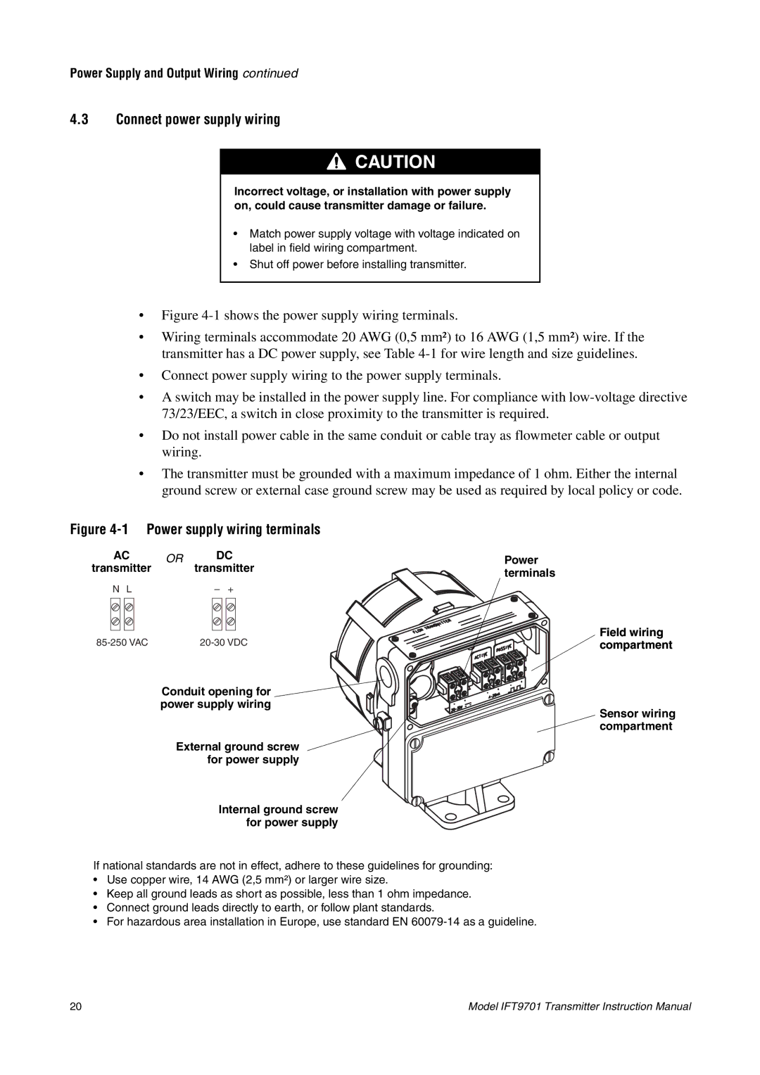
•Figure 4-1 shows the power supply wiring terminals.
•Wiring terminals accommodate 20 AWG (0,5 mm²) to 16 AWG (1,5 mm²) wire. If the transmitter has a DC power supply, see Table 4-1 for wire length and size guidelines.
•Connect power supply wiring to the power supply terminals.
•A switch may be installed in the power supply line. For compliance with low-voltage directive 73/23/EEC, a switch in close proximity to the transmitter is required.
•Do not install power cable in the same conduit or cable tray as flowmeter cable or output wiring.
•The transmitter must be grounded with a maximum impedance of 1 ohm. Either the internal ground screw or external case ground screw may be used as required by local policy or code.
Figure 4-1 Power supply wiring terminals
AC | OR | DC | Power | |
transmitter | transmitter | |||
| terminals | |||
|
|
| ||
N L |
| – + |
| |
| Field wiring | |||
| compartment |
Conduit opening for ![]()
power supply wiring
Sensor wiring compartment
External ground screw for power supply
Internal ground screw for power supply
If national standards are not in effect, adhere to these guidelines for grounding:
•Use copper wire, 14 AWG (2,5 mm²) or larger wire size.
•Keep all ground leads as short as possible, less than 1 ohm impedance.
•Connect ground leads directly to earth, or follow plant standards.
•For hazardous area installation in Europe, use standard EN
20 | Model IFT9701 Transmitter Instruction Manual |