Troubleshooting continued
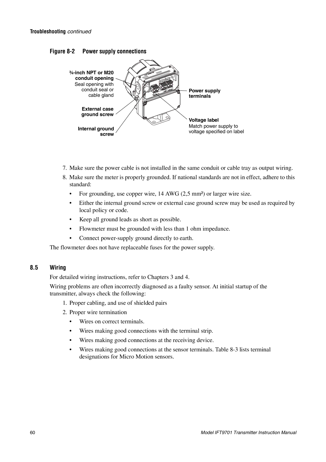
Figure 8-2 Power supply connections
| ||
conduit opening |
| |
Seal opening with |
| |
conduit seal or | Power supply | |
cable gland | terminals | |
External case |
| |
ground screw | Voltage label | |
| ||
Internal ground | Match power supply to | |
voltage specified on label | ||
screw | ||
|
7.Make sure the power cable is not installed in the same conduit or cable tray as output wiring.
8.Make sure the meter is properly grounded. If national standards are not in effect, adhere to this standard:
•For grounding, use copper wire, 14 AWG (2,5 mm²) or larger wire size.
•Either the internal ground screw or external case ground screw may be used as required by local policy or code.
•Keep all ground leads as short as possible.
•Flowmeter must be grounded with less than 1 ohm impedance.
•Connect
The flowmeter does not have replaceable fuses for the power supply.
8.5Wiring
For detailed wiring instructions, refer to Chapters 3 and 4.
Wiring problems are often incorrectly diagnosed as a faulty sensor. At initial startup of the transmitter, always check the following:
1.Proper cabling, and use of shielded pairs
2.Proper wire termination
•Wires on correct terminals.
•Wires making good connections with the terminal strip.
•Wires making good connections at the receiving device.
•Wires making good connections at the sensor terminals. Table
60 | Model IFT9701 Transmitter Instruction Manual |