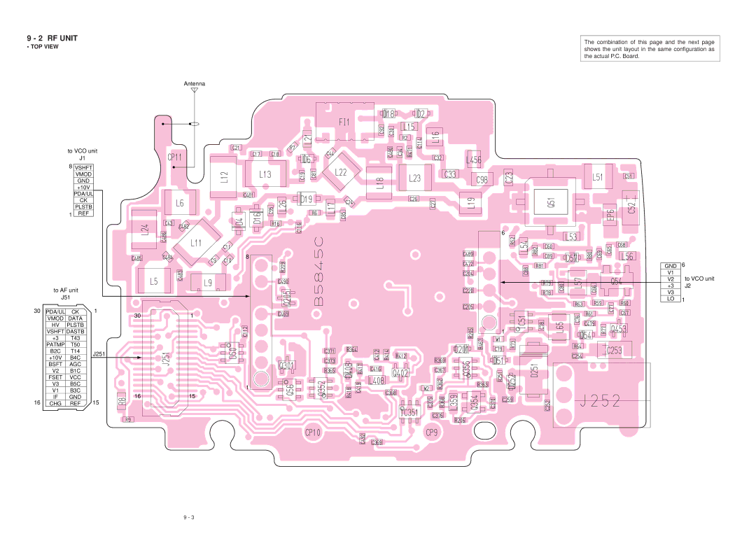
9 - 2 RF UNIT | The combination of this page and the next page | |
• TOP VIEW | ||
shows the unit layout in the same configuration as | ||
| ||
| the actual P.C. Board. | |
|
|
Antenna
|
| to VCO unit |
|
| ||
|
|
| J1 |
|
|
|
|
| 8 VSHFT |
|
|
| |
|
|
| VMOD |
|
|
|
|
|
| GND |
|
|
|
|
|
| +10V |
|
|
|
|
|
| PDA/UL |
|
| |
|
|
| CK |
|
|
|
|
|
| PLSTB |
|
|
|
|
| 1 | REF |
|
|
|
|
|
|
|
| 6 |
|
|
|
|
|
| 8 |
|
|
|
|
|
| GND | 6 |
|
|
|
|
| V1 | to VCO unit |
|
|
|
|
| V2 | |
| to AF unit |
| +3 | J2 | ||
|
| V3 |
| |||
| J51 |
|
|
| ||
|
|
| LO | 1 | ||
30 | PDA/UL | CK | 1 | 1 |
| |
| VMOD | DATA | 30 |
| ||
|
|
|
| |||
| HV | PLSTB |
|
|
| |
| VSHFT DASTB |
| 1 |
| ||
| +3 | T43 |
|
|
| |
| PATMP | T50 |
|
|
| |
| B2C | T14 | J251 |
|
| |
| +10V | B4C |
|
| ||
|
|
|
| |||
| BSFT | AGC |
|
|
| |
| V2 | B1C |
|
|
| |
| FSET | VCC |
|
|
| |
| V3 | B5C |
| 1 |
| |
| V1 | B3C |
|
| ||
| 16 | 15 |
| |||
| IF | GND |
| |||
16 | CHG | REF | 15 |
|
| |
9 - 3