SECTION 9 BOARD LAYOUTS
9 - 1 LOGIC UNIT
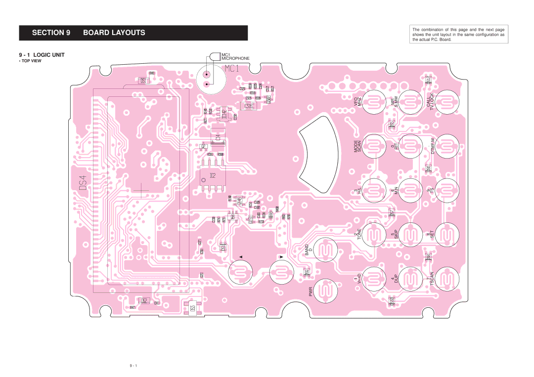
• TOP VIEW
MC1
MICROPHONE
The combination of this page and the next page shows the unit layout in the same configuration as the actual P.C. Board.
VFO MHZ | MR S.MW | CALL TV LOCK |
MODE SCAN | 0 RIT | . DTMF.M |
3 H/L | 6 M.N | 9 TS |
2 TONE | 5 SKIP | 8 SET |
D
![]() BAND
BAND
V | 4 DUP | 7 TSCAN |
D |
|
|
↔ |
|
|
1 |
|
|
PWR |
9 - 1