GENERAL

6 SEALED SYSTEM REQUIREMENTS - continued

7.Mains Connection

There must be no direct connection to the mains water supply or to the water storage tank supplying domestic water, even through a non-return valve, without the approval of the local water authority.

8.Filling

The system may be filled by one of the following methods:

a. Through a cistern, used for no other purposes, via a ball valve permanently connected directly to a service pipe and / or a cold water distributing pipe.

The static head available from the cistern should be adequate to provide the desired initial system design pressure. The cold feed pipe from the cistern should include a non-return valve and a stop valve with an automatic air vent connected between them, the stop valve being located between the system and the automatic air vent. The stop valve may remain open during normal operation of the system if automatic water make-up is required.

b. Through a self-contained unit comprising a cistern, pressure booster pump (if required) and, if necessary, an automatic pressure reducing valve and flow restrictor. The cistern should be supplied through a temporary connection from a service pipe or cold water distributing pipe.

This unit may remain permanently connected to the heating system to provide limited automatic water make-up. Where the temporary connection is supplied from a service pipe or distributing pipe which also supplies other draw-off points at a lower level then a double check valve shall be installed upstream of the draw-off point.

c. Through a temporary hose connection from a draw-off tap supplied from a service pipe under mains pressure. Where the mains pressure is excessive a pressure-reducing valve shall be used to facilitate filling.

The following fittings shall form a permanent part of the system and shall be fitted in the order stated:

A stop valve complying with the requirements of BS. 1010, Part 2 (the hose from the draw-off tap shall be connected to this fitting).

A test cock.

A double check valve of an approved type.

Thoroughly flush out the whole of the system with cold water, without the pump in position.

With the pump fitted, fill and vent the system until the pressure gauge registers 1.5 bar (21.5lb/in2).

Examine for leaks.

Check the operation of the safety valve by manually raising the water pressure until the valve lifts. This should occur within ± 0.3 bar (± 4.3lb/in2.) of the pre-set lift pressure.

Release water from the system until the initial system design pressure is reached.

Light the boiler and heat the system to the maximum working temperature. Examine for leaks.

Turn off the boiler and drain the system while still hot.

Refill and vent the system.

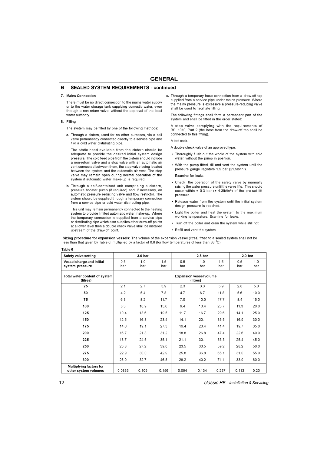
Sizing procedure for expansion vessels: The volume of the expansion vessel (litres) fitted to a sealed system shall not be less than that given by Table 6, multiplied by a factor of 0.8 (for flow temperatures of less than 88 oC).

Table 6

Safety valve setting


3.0 bar


2.5 bar


2.0 bar

Vessel charge and initial

0.5

1.0

1.5

0.5

1.0

1.5

0.5

1.0


system pressure

bar

bar

bar

bar

bar

bar

bar

bar


Total water content of system


Expansion vessel volume


(litres)


(litres)


25

2.1

2.7

3.9

2.3

3.3

5.9

2.8

5.0


50

4.2

5.4

7.8

4.7

6.7

11.8

5.6

10.0


75

6.3

8.2

11.7

7.0

10.0

17.7

8.4

15.0


100

8.3

10.9

15.6

9.4

13.4

23.7

11.3

20.0


125

10.4

13.6

19.5

11.7

16.7

29.6

14.1

25.0


150

12.5

16.3

23.4

14.1

20.1

35.5

16.9

30.0


175

14.6

19.1

27.3

16.4

23.4

41.4

19.7

35.0


200

16.7

21.8

31.2

18.8

26.8

47.4

22.6

40.0


225

18.7

24.5

35.1

21.1

30.1

53.3

25.4

45.0


250

20.8

27.2

39.0

23.5

33.5

59.2

28.2

50.0


275

22.9

30.0

42.9

25.8

36.8

65.1

31.0

55.0


300

25.0

32.7

46.8

28.2

40.2

71.1

33.9

60.0


Multiplying factors for


other system volumes

0.0833

0.109

0.156

0.094

0.134

0.237

0.113

0.20


12

classic HE - Installation & Servicing

Page 12
Image 12
IDEAL INDUSTRIES HE9, HE18, HE12, HE15 manual Sealed System Requirements

HE12, HE15, HE18, HE9 specifications

The IDEAL INDUSTRIES HE series, comprising the HE24, HE18, HE15, and HE12 models, represents a significant advancement in the field of electrical testing and measurement tools. These versatile testers stand out in professional environments for their high accuracy, user-friendly interfaces, and advanced features designed to enhance efficiency and reliability in electrical inspections.

The HE24 is the flagship model, boasting an extensive range of functionalities. It includes advanced digital multimeter capabilities, allowing for precise measurements of voltage, current, and resistance. Its True RMS feature ensures accurate readings, even with non-linear loads. The HE24 also incorporates advanced connectivity options, including Bluetooth technology, enabling users to transfer data wirelessly to smartphones or tablets for further analysis. The large, backlit display enhances visibility in various lighting conditions, making it an ideal tool for both indoor and outdoor use.

The HE18 model, while slightly more streamlined than the HE24, still offers robust capabilities. It features multiple testing modes, including continuity and diode testing, catering to a wide range of electrical tasks. The HE18 also utilizes a user-friendly interface, allowing technicians to navigate easily through various functions. Equipped with a protective rubber housing, this model is durable and built to withstand the rigors of frequent use on job sites.

The HE15 and HE12 models represent the compact, entry-level offerings in the HE series. Designed for the budget-conscious user, these models retain essential functionalities such as basic voltage and current measuring capabilities while prioritizing ease of use. The HE15 includes a simple LED indicator to signal when measurements are being taken, promoting straightforward operation. Additionally, the HE12 features a lightweight design, making it the perfect tool for on-the-go technicians.

All models in the IDEAL INDUSTRIES HE series are engineered with safety in mind, adhering to stringent international testing standards. They provide superior insulation resistance and a high degree of accuracy, mitigating the risks associated with electrical work. Furthermore, their IP-rated enclosures ensure protection against dust and moisture, enhancing longevity.

In conclusion, the IDEAL INDUSTRIES HE24, HE18, HE15, and HE12 series represent a comprehensive range of electrical testing tools that cater to professionals' varied needs. With their combination of advanced features, user-friendly designs, and safety compliance, these models are excellent choices for any electrical technician aiming for accuracy and efficiency in their work.