INSTALLATION

INSTALLATION

36 GAS CONNECTION

Refer to 'Gas Supply ', page 8.

Refer to Frame 2 for gas inlet service dimensions.

Aminimum pressure of 20 mbar MUST be available at the boiler inlet with the boiler operating. The main gas cock is on the left hand side of the gas control valve, as shown. To facilitate connection the gas cock may be removed from the gas control valve.

37 WATER CONNECTIONS

1.Remove the plastic plugs from the flow and return pipes.

2.Make all water connections and check for water soundness.

38 CONDENSATE DRAIN

Refer also to the British Gas document: 'Guidance Notes for the Installation of Domestic Gas Condensing Boilers' (1989).

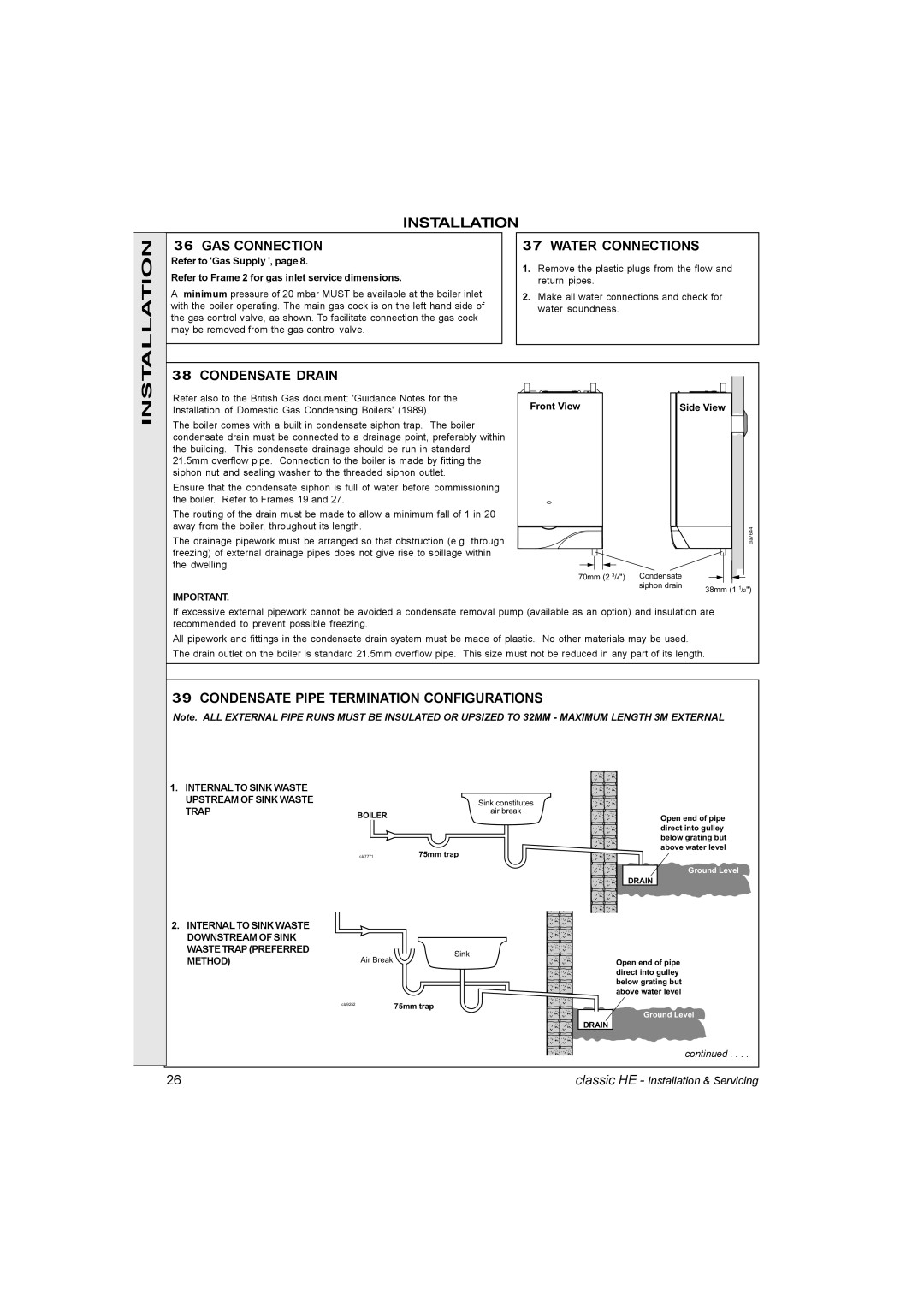
The boiler comes with a built in condensate siphon trap. The boiler condensate drain must be connected to a drainage point, preferably within the building. This condensate drainage should be run in standard 21.5mm overflow pipe. Connection to the boiler is made by fitting the siphon nut and sealing washer to the threaded siphon outlet.

Ensure that the condensate siphon is full of water before commissioning the boiler. Refer to Frames 19 and 27.

The routing of the drain must be made to allow a minimum fall of 1 in 20 away from the boiler, throughout its length.

The drainage pipework must be arranged so that obstruction (e.g. through freezing) of external drainage pipes does not give rise to spillage within the dwelling.

IMPORTANT.


Front View


Side View


cla7644

70mm (2 3/4") Condensate


siphon drain

38mm (1 1/2")

If excessive external pipework cannot be avoided a condensate removal pump (available as an option) and insulation are recommended to prevent possible freezing.

All pipework and fittings in the condensate drain system must be made of plastic. No other materials may be used. The drain outlet on the boiler is standard 21.5mm overflow pipe. This size must not be reduced in any part of its length.

39 CONDENSATE PIPE TERMINATION CONFIGURATIONS

Note. ALL EXTERNAL PIPE RUNS MUST BE INSULATED OR UPSIZED TO 32MM - MAXIMUM LENGTH 3M EXTERNAL

1. INTERNAL TO SINK WASTE

UPSTREAM OF SINK WASTE

Sink constitutes

TRAP

BOILER

air break

Open end of pipe direct into gulley below grating but above water level

2.INTERNAL TO SINK WASTE DOWNSTREAM OF SINK WASTE TRAP (PREFERRED METHOD)

cla7771

75mm trap

Sink

Air Break

cla9252

75mm trap


DRAIN

Ground Level

DRAIN

Open end of pipe direct into gulley below grating but above water level

Ground Level

continued . . . .

26

classic HE - Installation & Servicing

Page 26
Image 26
IDEAL INDUSTRIES HE12, HE9 GAS Connection, Water Connections, Condensate Drain, Condensate Pipe Termination Configurations

HE12, HE15, HE18, HE9 specifications

The IDEAL INDUSTRIES HE series, comprising the HE24, HE18, HE15, and HE12 models, represents a significant advancement in the field of electrical testing and measurement tools. These versatile testers stand out in professional environments for their high accuracy, user-friendly interfaces, and advanced features designed to enhance efficiency and reliability in electrical inspections.

The HE24 is the flagship model, boasting an extensive range of functionalities. It includes advanced digital multimeter capabilities, allowing for precise measurements of voltage, current, and resistance. Its True RMS feature ensures accurate readings, even with non-linear loads. The HE24 also incorporates advanced connectivity options, including Bluetooth technology, enabling users to transfer data wirelessly to smartphones or tablets for further analysis. The large, backlit display enhances visibility in various lighting conditions, making it an ideal tool for both indoor and outdoor use.

The HE18 model, while slightly more streamlined than the HE24, still offers robust capabilities. It features multiple testing modes, including continuity and diode testing, catering to a wide range of electrical tasks. The HE18 also utilizes a user-friendly interface, allowing technicians to navigate easily through various functions. Equipped with a protective rubber housing, this model is durable and built to withstand the rigors of frequent use on job sites.

The HE15 and HE12 models represent the compact, entry-level offerings in the HE series. Designed for the budget-conscious user, these models retain essential functionalities such as basic voltage and current measuring capabilities while prioritizing ease of use. The HE15 includes a simple LED indicator to signal when measurements are being taken, promoting straightforward operation. Additionally, the HE12 features a lightweight design, making it the perfect tool for on-the-go technicians.

All models in the IDEAL INDUSTRIES HE series are engineered with safety in mind, adhering to stringent international testing standards. They provide superior insulation resistance and a high degree of accuracy, mitigating the risks associated with electrical work. Furthermore, their IP-rated enclosures ensure protection against dust and moisture, enhancing longevity.

In conclusion, the IDEAL INDUSTRIES HE24, HE18, HE15, and HE12 series represent a comprehensive range of electrical testing tools that cater to professionals' varied needs. With their combination of advanced features, user-friendly designs, and safety compliance, these models are excellent choices for any electrical technician aiming for accuracy and efficiency in their work.