Electrical connections
The cooker must be connected to the mains electricity supply. It is designed to operate with alternating current at the voltage and frequency indicated on the data plate (see the following page).
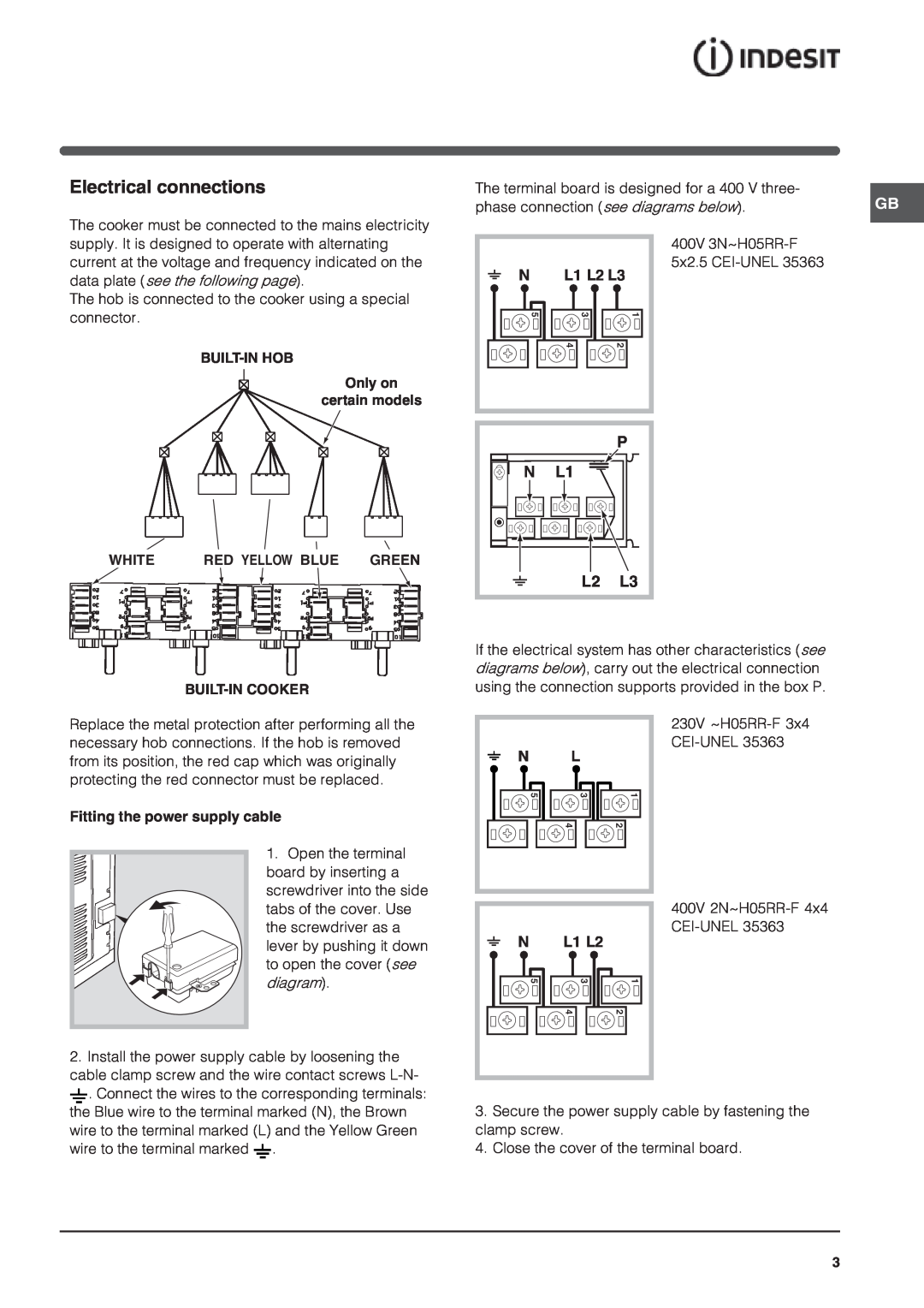
The hob is connected to the cooker using a special connector.
Only on
certain models
| WHITE | RED YELLOW BLUE GREE | N |
Replace the metal protection after performing all the necessary hob connections. If the hob is removed from its position, the red cap which was originally protecting the red connector must be replaced.
Fitting the power supply cable
1. Open the terminal board by inserting a screwdriver into the side
The terminal board is designed for a 400 V three- | GB |
phase connection (see diagrams below). |
400V
5x2.5
N L1 L2 L3
5 | 3 | 1 |
| 4 | 2 |
|
| P |
N | L1 |
|
| L2 | L3 |
If the electrical system has other characteristics (see diagrams below), carry out the electrical connection using the connection supports provided in the box P.
230V
N L
5 | 3 | 1 |
4 | 2 |
tabs of the cover. Use the screwdriver as a lever by pushing it down to open the cover (see
diagram).
N | L1 L2 |
5 | 3 | 1 |
| 4 | 2 |
400V
2.Install the power supply cable by loosening the cable clamp screw and the wire contact screws ![]() . Connect the wires to the corresponding terminals: the Blue wire to the terminal marked (N), the Brown wire to the terminal marked (L) and the Yellow Green wire to the terminal marked
. Connect the wires to the corresponding terminals: the Blue wire to the terminal marked (N), the Brown wire to the terminal marked (L) and the Yellow Green wire to the terminal marked ![]() .
.
3.Secure the power supply cable by fastening the clamp screw.
4.Close the cover of the terminal board.
3