Manuals
/
Integra
/
Home Audio
/
Stereo Receiver
Integra
DTR-7.2 Connections, Connecting a television monitor or projector, Monitor Out, optical
Models:
DTR-7.2
1
19
76
76
Download
76 pages
20.42 Kb
16
17
18
19
20
21
22
23
Page 19
Image 19
Page 18
Page 20
Page 19
Image 19
Page 18
Page 20
Contents
Remote controller
Contents
Before using
Setup and operation
AVIS
Important Safeguards
1. Recording Copyright
Precautions
4. Power
For U.S. models Note to CATV system installer
Contents
Contents
Audio/Video Features
Features
Supplied accessories
Amplifier Features
Installing the remote controller batteries
Before using this unit
Using the remote controller
Front panel
Front panel facilities
Front panel display
Front panel facilities
Front panel facilities
Remote controller
Remote controller
DIGITAL INPUT/OUTPUT coaxial and optical
Rear panel facilities
A-BUS
Rear panel facilities
PRE OUT
COMPONENT VIDEO INPUT/OUTPUT
Rear panel facilities
REMOTE CONTROL
Power on/ready function
Power off function
MULTI CHANNEL INPUT
Rear panel facilities
IR IN/OUT
VIDEO IN/OUT
Connecting your audio components
Connections
Connecting your video components
Connections
Connections
6. Connecting a video cassette recorder VIDEO
Digital output
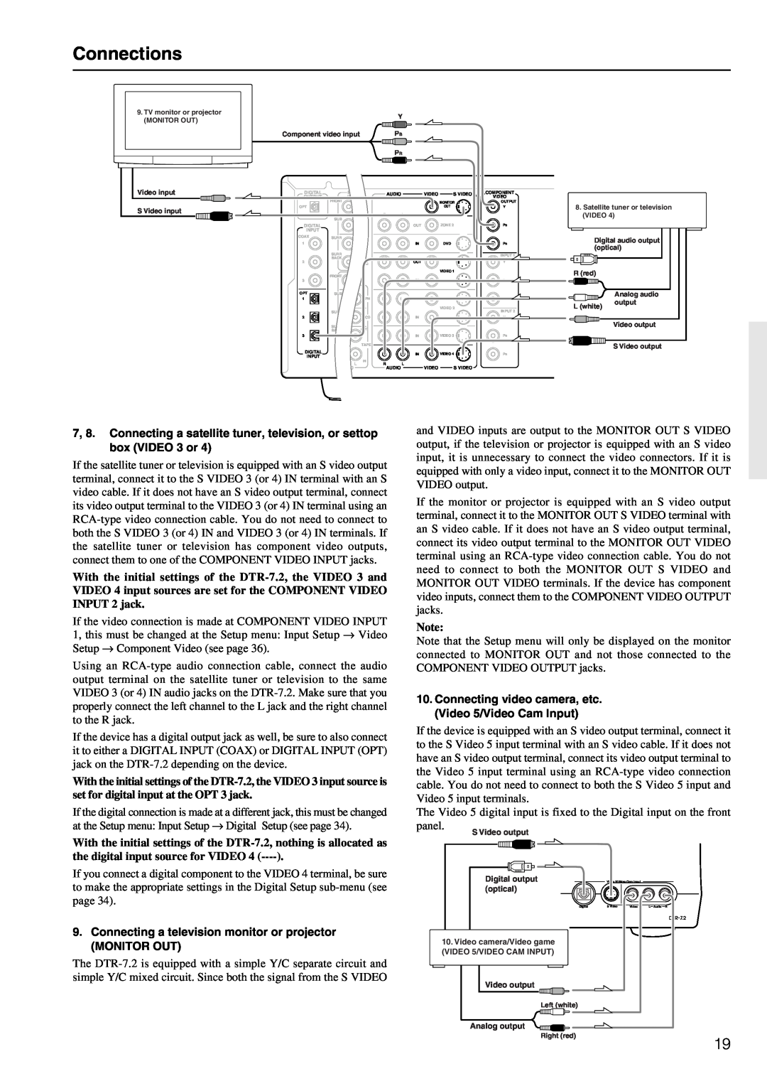
9.Connecting a television monitor or projector
Connections
MONITOR OUT
Ideal speaker configuration
Connecting speakers
Speaker placement
Connecting speakers
Assembling the AM loop antenna
Connecting antennas
Connecting the AM antenna cable
Connecting the included antennas
Directional linkage
Connecting antennas
Connecting an FM outdoor antenna
Connecting an AM outdoor antenna
When using the ZONE 2 OUT terminals
Connecting the remote zone Zone 2 speakers
other component
from connecting block
Connecting the power
Button on DTR-7.2
Setup menus
Navigating through the Setup menu
Button on remote controller
Basic Menu
Setup menus
Advanced Menu
0. Hardware Setup menu
Hardware Setup
1. Speaker Setup menu
Speaker Setup
1-2.Speaker Distance sub-menu
Speaker Setup
1-3.Level Calibration sub-menu
Speaker Setup
a. Bass Peak Level Limiter
Speaker Setup
1-4.Bass Peak Level
Bass Peak Level Manager* sub-menu
2. Input Setup menu
Input Setup
2-2.Multichannel Setup sub-menu
Input Setup
b. Component Video
Input Setup
2-3.Video Setup sub-menu
a. Video
2-4.Character Input sub-menu
Input Setup
2-5.Intelli Volume sub-menu
a. Intelli Volume
Analog/PCM
Input Setup
2-6.Listening Mode Preset sub-menu
Input source signal
a. Analog/PCM
Input Setup
2-7.12V Trigger Setup sub-menu
Input Setup
3. Audio Adjust Setup menu
Audio Adjust
Audio Adjust
3-6.Mono Setup
Audio Adjust
3-8.Surround Setup
Audio Adjust
Parameter
Audio Adjust
Setting
3-10. 3-11. 3-12. 3-13
4. Preference menu
Preference
4-4.OSD Position sub-menu
Preference
4-2.Headphones Level Setup sub-menu
4-3.OSD Setup sub-menu
Tuning into a radio station
Listening to Radio Broadcasts
Listening to a stereo radio station FM mode
Erasing a preset radio station
Listening to Radio Broadcasts
Presetting a radio station
Selecting a preset radio station
Temporarily turning off the sound
Enjoying music or videos with the DTR-7.2
Adjusting the bass and treble
Listening with headphones
Changing the listening mode
Enjoying music or videos with the DTR-7.2
Enjoying music or videos with the DTR-7.2
Switching the display
Adjusting the brightness of the front display
Using the sleep time remote controller only
Changing the audio mode
Enjoying music or videos with the DTR-7.2
Enjoying the multichannel output
Playing music using the buttons on the DTR-7.2
Enjoying music in the remote zone
1.Press the CD input source button
Recording a source
Video
Overview
Using remote controller
Controlling an Integra/Onkyo CD player
Using remote controller
ON STDBY
Using remote controller
DVD MODE SETUP VOL MENU MUTING SUBTITLE
Controlling an Integra/Onkyo DVD player
1 to 9, 0, --/--- Numeric keys
Using remote controller
Controlling an Integra/Onkyo MD recorder
SAT, CABLE, VCR, and TV MODE buttons
Learning a pre-programmingcode
Learning a pre-programmingcode
SETTING No
Learning a pre-programmingcode
SETTING No
SETTING No
CABLE MODE Cable Mode
Operating your programmed remote controller
DVD MODE DVD Player Mode
SAT MODE Satellite Tuner Mode
VCR MODE VCR Mode
Operating your programmed remote controller
TV MODE TV Mode
Programming procedure
Page
ENTER
Erasing the programmed command from one button
ENTER
3.Press and release the same button again
What is a Macro function?
Using a Macro function
Programming the Direct Macro function
Using a Macro function
Running a Direct Macro function
2.Press the MODE MACRO button again
Using a Macro function
Erasing a macro from the MODE MACRO button
MODE MACRO
Using a Macro function
All channels
Specifications
REMOTE CONTROLLER
AMPLIFIER SECTION
FM/AM TUNER
Troubleshooting guide
POWER
SPEAKERS
OTHER
Troubleshooting guide
REMOTE CONTROLLER
VIDEO and AUDIO
Memo
Memo
SN 29343210A
Integra Division of ONKYO U.S.A. CORPORATION
Integra Division of ONKYO CORPORATION
Tel 072-831-8111Fax
Top
Page
Image
Contents