AUTOMOTIVE 80C51FA/83C51FA
270501 ±6
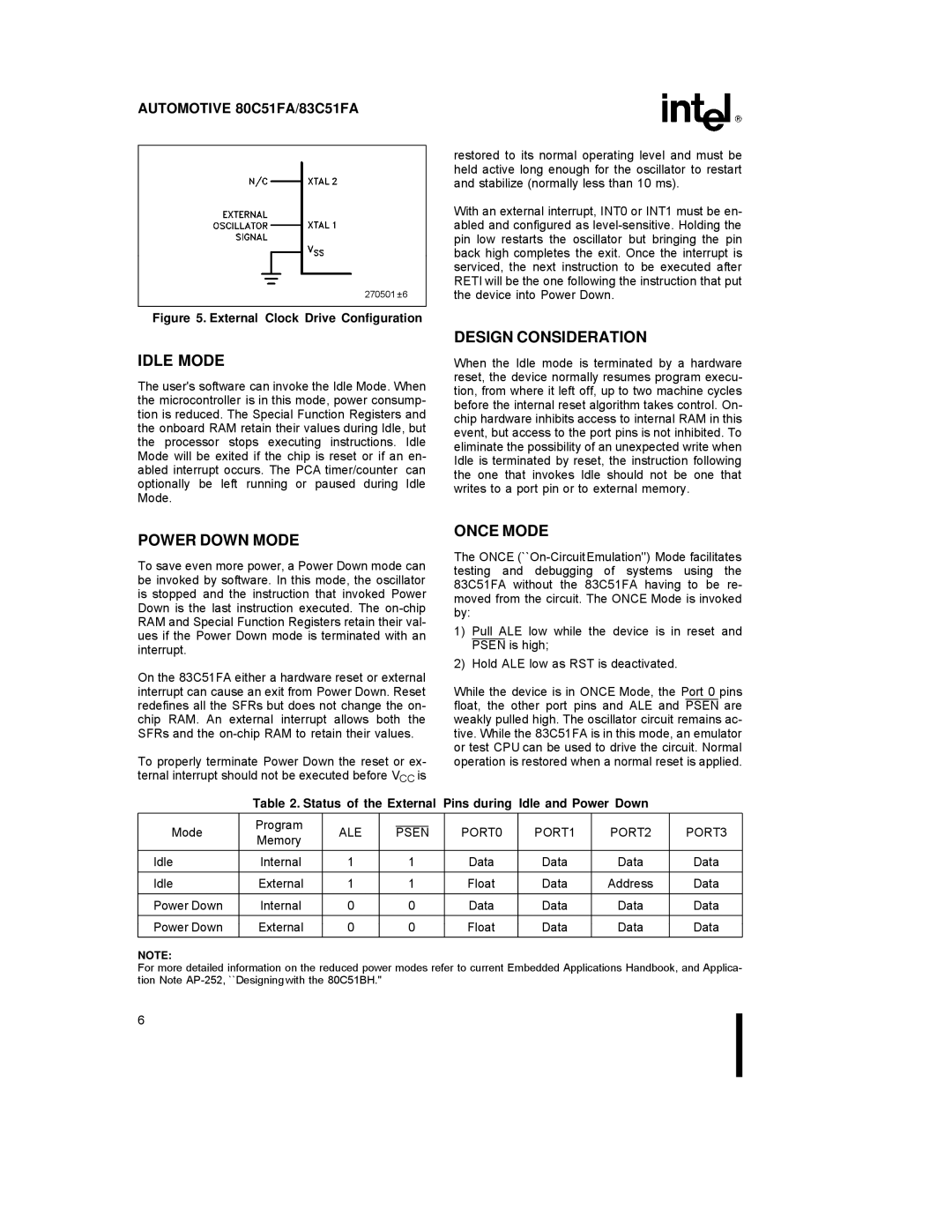
Figure 5. External Clock Drive Configuration
IDLE MODE
The user's software can invoke the Idle Mode. When the microcontroller is in this mode, power consump- tion is reduced. The Special Function Registers and the onboard RAM retain their values during Idle, but the processor stops executing instructions. Idle Mode will be exited if the chip is reset or if an en- abled interrupt occurs. The PCA timer/counter can optionally be left running or paused during Idle Mode.
restored to its normal operating level and must be held active long enough for the oscillator to restart and stabilize (normally less than 10 ms).
With an external interrupt, INT0 or INT1 must be en- abled and configured as
DESIGN CONSIDERATION
When the Idle mode is terminated by a hardware reset, the device normally resumes program execu- tion, from where it left off, up to two machine cycles before the internal reset algorithm takes control. On- chip hardware inhibits access to internal RAM in this event, but access to the port pins is not inhibited. To eliminate the possibility of an unexpected write when Idle is terminated by reset, the instruction following the one that invokes Idle should not be one that writes to a port pin or to external memory.
POWER DOWN MODE
To save even more power, a Power Down mode can be invoked by software. In this mode, the oscillator is stopped and the instruction that invoked Power Down is the last instruction executed. The
On the 83C51FA either a hardware reset or external interrupt can cause an exit from Power Down. Reset redefines all the SFRs but does not change the on- chip RAM. An external interrupt allows both the SFRs and the
To properly terminate Power Down the reset or ex- ternal interrupt should not be executed before VCC is
ONCE MODE
The ONCE
1)Pull ALE low while the device is in reset and PSEN is high;
2)Hold ALE low as RST is deactivated.
While the device is in ONCE Mode, the Port 0 pins float, the other port pins and ALE and PSEN are weakly pulled high. The oscillator circuit remains ac- tive. While the 83C51FA is in this mode, an emulator or test CPU can be used to drive the circuit. Normal operation is restored when a normal reset is applied.
Table 2. Status of the External Pins during Idle and Power Down
| Program |
|
|
|
|
|
|
|
|
Mode | ALE |
| PSEN | PORT0 | PORT1 | PORT2 | PORT3 | ||
Memory |
| ||||||||
|
|
|
|
|
|
|
|
| |
Idle | Internal | 1 |
| 1 |
| Data | Data | Data | Data |
Idle | External | 1 |
| 1 |
| Float | Data | Address | Data |
Power Down | Internal | 0 |
| 0 |
| Data | Data | Data | Data |
Power Down | External | 0 |
| 0 |
| Float | Data | Data | Data |
NOTE:
For more detailed information on the reduced power modes refer to current Embedded Applications Handbook, and Applica- tion Note
6