English
7) SATA0/SATA1 (Serial ATA Connector, Controlled by SiS964)
Serial ATA can provide 150MB/s transfer rate. Please refer to the BIOS setting for the Serial ATA and install the proper driver in order to work properly.
|
| Pin No. | Definition |
|
| 1 | GND |
|
| 2 | TXP |
|
| 3 | TXN |
1 | 7 | 4 | GND |
| S_ATA | 5 | RXN |
| (Control by SiS964) | 6 | RXP |
|
| 7 | GND |
For more detailed Serial ATA RAID setup information, please visit our website at http:\\www.gigabyte.com.tw.
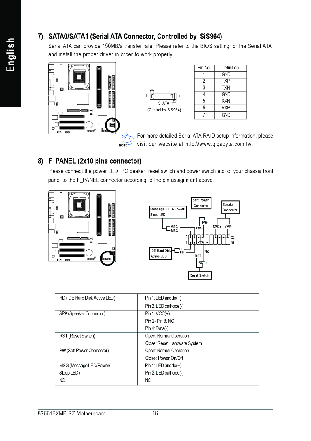
8) F_PANEL (2x10 pins connector)
Please connect the power LED, PC peaker, reset switch and power switch etc. of your chassis front panel to the F_PANEL connector according to the pin assignment above.
Message LED/Power/ Sleep LED
MSG- ![]() MSG+
MSG+
2
1
IDE Hard Disk |
|
|
|
| HD+ |
Active LED |
|
|
|
| HD- |
|
|
|
|
|
Soft Power Connector
PW-
PW+
NC
RST- RST+
Speaker
Connector
SPK+ SPK-
20
19
Reset Switch
HD (IDE Hard Disk Active LED) | Pin 1: LED anode(+) |
| Pin 2: LED |
|
|
SPK (Speaker Connector) | Pin 1: VCC(+) |
| Pin 2- Pin 3: NC |
| Pin 4: |
|
|
RST (Reset Switch) | Open: Normal Operation |
| Close: Reset Hardware System |
PW (Soft Power Connector) | Open: Normal Operation |
| Close: Power On/Off |
|
|
MSG (Message LED/Power/ | Pin 1: LED anode(+) |
Sleep LED) | Pin 2: LED |
|
|
NC | NC |
|
|
- 16 - |