Rear Panel Connectors
The network interface, a terminal port for configuration and management, an alarm
1 | 2 | 3 | 4 | 5 | 6 |
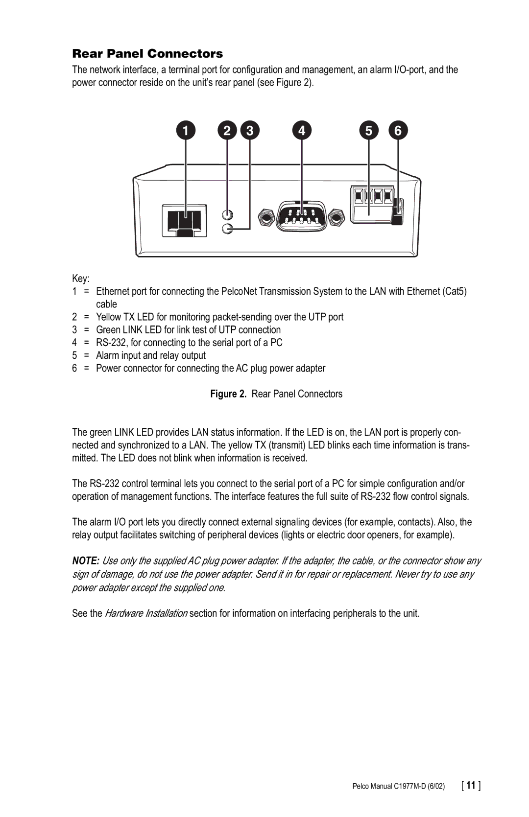
Key:
1= Ethernet port for connecting the PelcoNet Transmission System to the LAN with Ethernet (Cat5) cable
2= Yellow TX LED for monitoring
3 = Green LINK LED for link test of UTP connection 4 =
6= Power connector for connecting the AC plug power adapter Figure 2. Rear Panel Connectors
The green LINK LED provides LAN status information. If the LED is on, the LAN port is properly con- nected and synchronized to a LAN. The yellow TX (transmit) LED blinks each time information is trans- mitted. The LED does not blink when information is received.
The
The alarm I/O port lets you directly connect external signaling devices (for example, contacts). Also, the relay output facilitates switching of peripheral devices (lights or electric door openers, for example).
NOTE: Use only the supplied AC plug power adapter. If the adapter, the cable, or the connector show any sign of damage, do not use the power adapter. Send it in for repair or replacement. Never try to use any power adapter except the supplied one.
See the Hardware Installation section for information on interfacing peripherals to the unit.
Pelco Manual | [ 11 ] |