AC Load and Signal Line Connection
AC Load and Signal Line Connection
Important: The following procedure should be used as a guide only. Ensure that the installation complies with the specific wiring rules applicable to your country or area of jurisdiction.
AC Output Connector
This is a two terminal barrier strip for use with up to #12 AWG wire. The two terminals, L1 & L2 are floating outputs, L1 or L2 can be grounded to simulate a neutral conductor. The barrier strip will accept a maximum lug width of 0.32 in. (8.1 mm). The recommended torque on the screw is 9 in- lbs.
Load Wiring
When selecting load wiring, consider the following factors:
•Current carrying capacity of the wire
•Maximum wire length
•Maximum ambient temperature
•Noise effects on signal lines
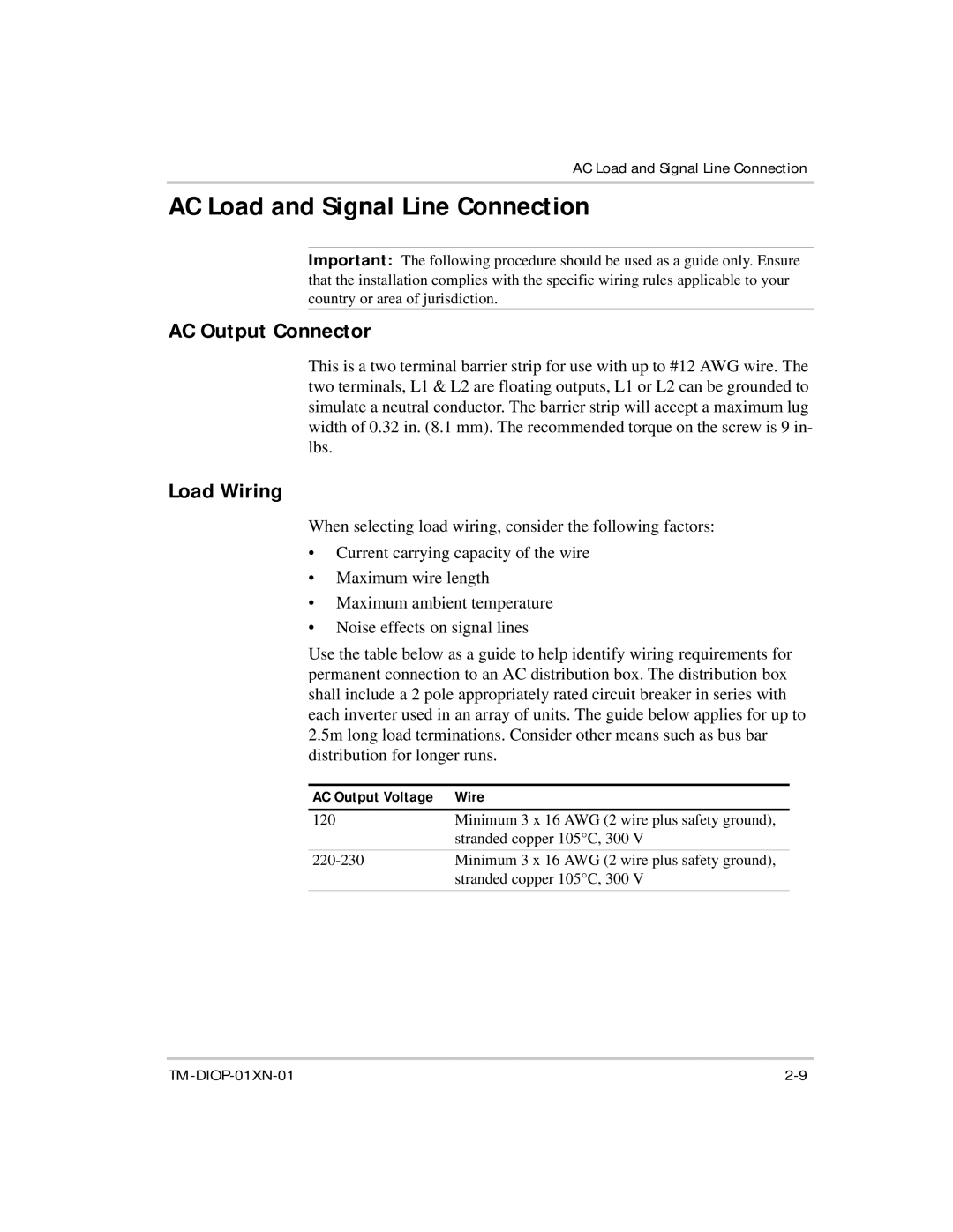
Use the table below as a guide to help identify wiring requirements for permanent connection to an AC distribution box. The distribution box shall include a 2 pole appropriately rated circuit breaker in series with each inverter used in an array of units. The guide below applies for up to 2.5m long load terminations. Consider other means such as bus bar distribution for longer runs.
AC Output Voltage | Wire |
120 | Minimum 3 x 16 AWG (2 wire plus safety ground), |
| stranded copper 105°C, 300 V |
Minimum 3 x 16 AWG (2 wire plus safety ground), | |
| stranded copper 105°C, 300 V |
