Rack Mount Frame Assembly and Installation
| L1 | 1 2 3 4 5 6 | 7 | |
| L2 | |||
| L1 |
| 2 3 4 5 6 | 7 |
| L2 | 1 | ||
| L1 |
|
|
|
| L2 | 1 2 3 4 5 6 | 7 | |
|
| |||
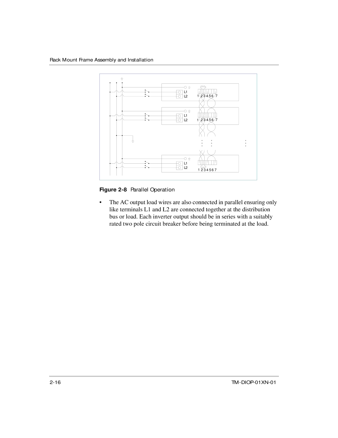
Figure | Parallel Operation |
|
|
|
•The AC output load wires are also connected in parallel ensuring only like terminals L1 and L2 are connected together at the distribution bus or load. Each inverter output should be in series with a suitably rated two pole circuit breaker before being terminated at the load.
