User Diagnostics
Diagnostic Guide
I
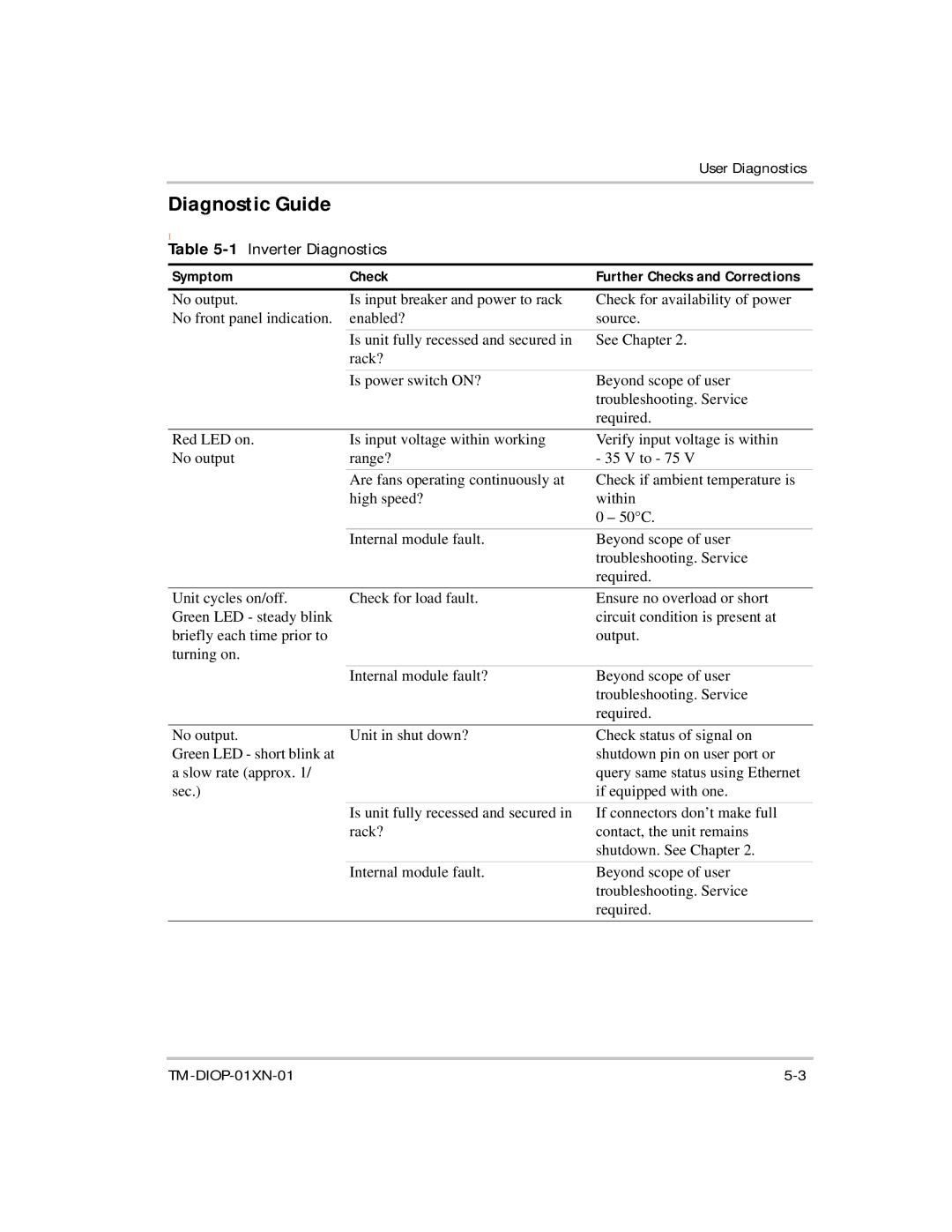
Table 5-1 Inverter Diagnostics
Symptom | Check | Further Checks and Corrections |
No output. | Is input breaker and power to rack | Check for availability of power |
No front panel indication. | enabled? | source. |
| Is unit fully recessed and secured in | See Chapter 2. |
| rack? |
|
| Is power switch ON? | Beyond scope of user |
|
| troubleshooting. Service |
|
| required. |
Red LED on. | Is input voltage within working | Verify input voltage is within |
No output | range? | - 35 V to - 75 V |
| Are fans operating continuously at | Check if ambient temperature is |
| high speed? | within |
|
| 0 – 50°C. |
| Internal module fault. | Beyond scope of user |
|
| troubleshooting. Service |
|
| required. |
Unit cycles on/off. | Check for load fault. |
Green LED - steady blink |
|
briefly each time prior to |
|
turning on. |
|
Ensure no overload or short circuit condition is present at output.
| Internal module fault? | Beyond scope of user |
|
| troubleshooting. Service |
|
| required. |
No output. | Unit in shut down? | Check status of signal on |
Green LED - short blink at |
| shutdown pin on user port or |
a slow rate (approx. 1/ |
| query same status using Ethernet |
sec.) |
| if equipped with one. |
| Is unit fully recessed and secured in | If connectors don’t make full |
| rack? | contact, the unit remains |
|
| shutdown. See Chapter 2. |
| Internal module fault. | Beyond scope of user |
|
| troubleshooting. Service |
|
| required. |
|
