AC Load and Signal Line Connection
User Line Connection
Overview
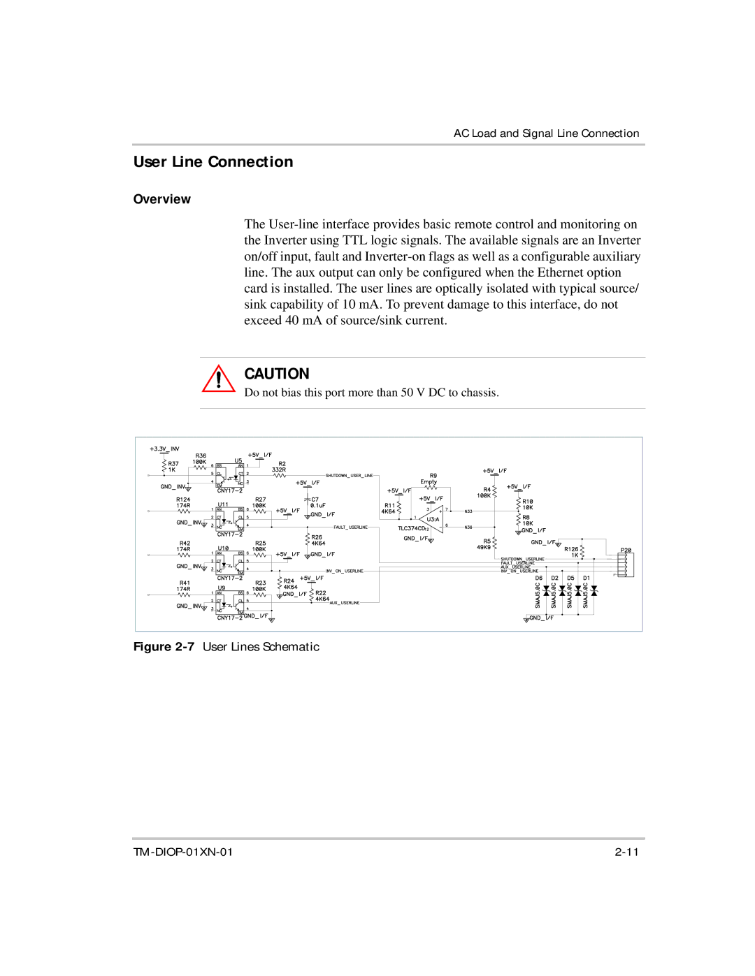
The User-line interface provides basic remote control and monitoring on the Inverter using TTL logic signals. The available signals are an Inverter on/off input, fault and Inverter-on flags as well as a configurable auxiliary line. The aux output can only be configured when the Ethernet option card is installed. The user lines are optically isolated with typical source/ sink capability of 10 mA. To prevent damage to this interface, do not exceed 40 mA of source/sink current.
CAUTION
Do not bias this port more than 50 V DC to chassis.
Figure 2-7 | User Lines Schematic |