Front Panel Connectors
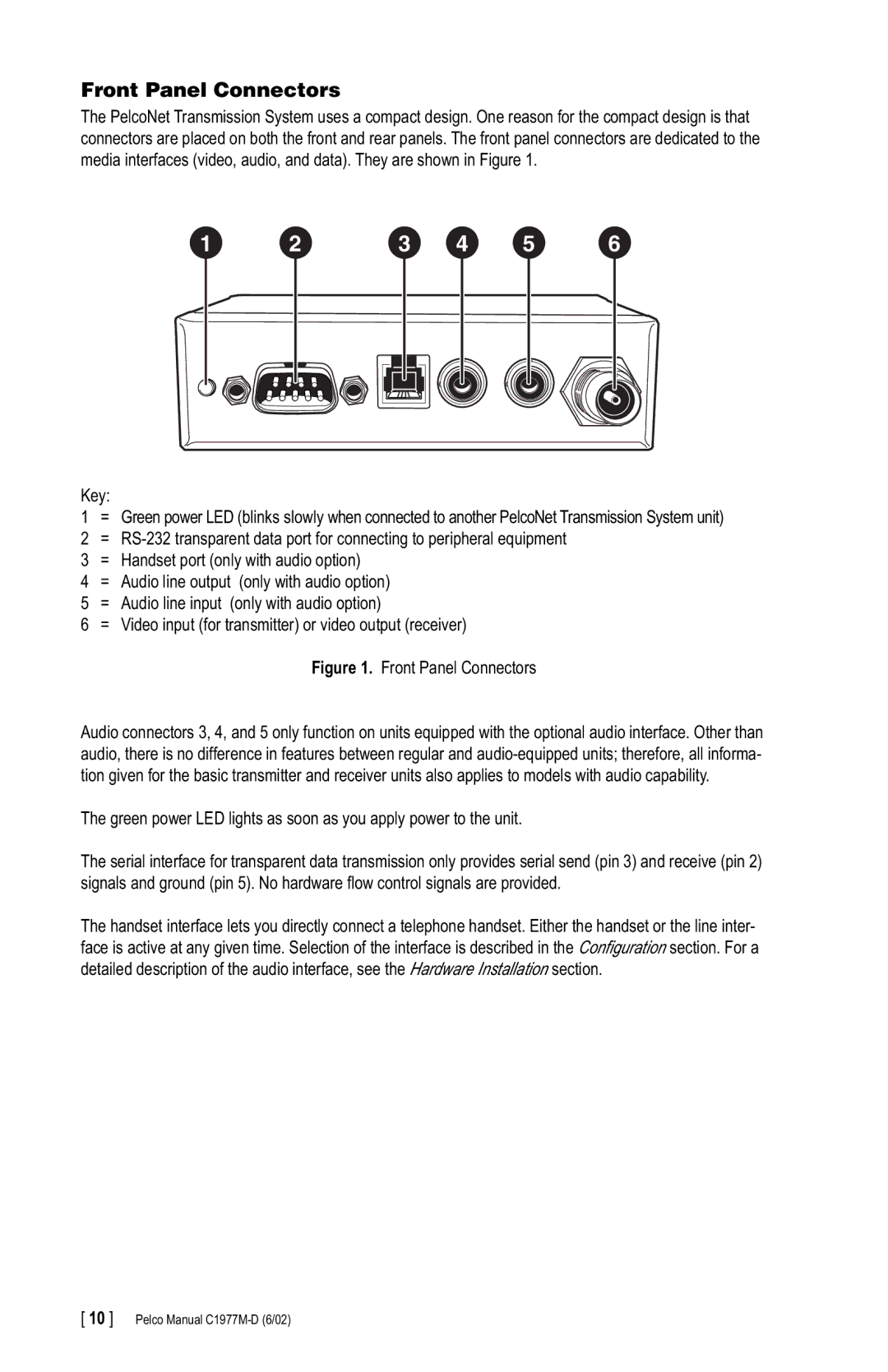
The PelcoNet Transmission System uses a compact design. One reason for the compact design is that connectors are placed on both the front and rear panels. The front panel connectors are dedicated to the media interfaces (video, audio, and data). They are shown in Figure 1.
1 | 2 | 3 | 4 | 5 | 6 |
Key:
1= Green power LED (blinks slowly when connected to another PelcoNet Transmission System unit)
2 =
4 | = | Audio line output (only with audio option) |
5 | = | Audio line input (only with audio option) |
6 | = Video input (for transmitter) or video output (receiver) | |
Figure 1. Front Panel Connectors
Audio connectors 3, 4, and 5 only function on units equipped with the optional audio interface. Other than audio, there is no difference in features between regular and
The green power LED lights as soon as you apply power to the unit.
The serial interface for transparent data transmission only provides serial send (pin 3) and receive (pin 2) signals and ground (pin 5). No hardware flow control signals are provided.
The handset interface lets you directly connect a telephone handset. Either the handset or the line inter- face is active at any given time. Selection of the interface is described in the Configuration section. For a detailed description of the audio interface, see the Hardware Installation section.
[ 10 ] Pelco Manual
