ATX12V Power Supply Design Guide
Version 2.0
3.2.9. Closed-loop Stability
The power supply shall be unconditionally stable under all line/load/transient load conditions including capacitive loads specified in Section 3.2.8. A minimum of 45 degrees phase margin and 10 dB gain margin is recommended at both the maximum and minimum loads.
3.2.10. +5 VDC / +3.3 VDC Power Sequencing
The +12 VDC and +5 VDC output levels must be equal to or greater than the +3.3 VDC output at all times during
3.2.11. Voltage Hold-up Time
The power supply should maintain output regulation per Section 3.2.1 despite a loss of input power at the
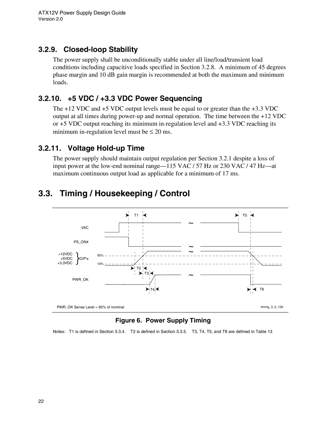
3.3. Timing / Housekeeping / Control
VAC |
| |
PS_ON# |
| |
+12VDC | 95% | |
+3.3VDC+5VDC }O/P's | ||
10% |
PWR_OK
T1
T2
T3 ![]()
![]() T4
T4 ![]()
T5
~
~
~
~
T6
PWR_OK Sense Level = 95% of nominal | timing_3_5_12b |
|
|
Figure 6. Power Supply Timing
Notes: T1 is defined in Section 3.3.4. T2 is defined in Section 3.3.5. T3, T4, T5, and T6 are defined in Table 13
22