ATX12V Power Supply Design Guide
Version 2.0
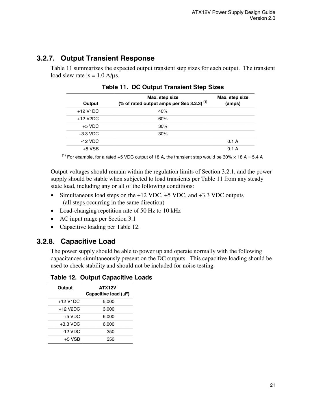
3.2.7. Output Transient Response
Table 11 summarizes the expected output transient step sizes for each output. The transient load slew rate is = 1.0 A/µs.
Table 11. DC Output Transient Step Sizes
| Max. step size | Max. step size |
Output | (% of rated output amps per Sec 3.2.3) (1) | (amps) |
|
|
|
+12 V1DC | 40% |
|
|
|
|
+12 V2DC | 60% |
|
|
|
|
+5 VDC | 30% |
|
|
|
|
+3.3 VDC | 30% |
|
|
|
|
| 0.1 A | |
|
|
|
+5 VSB |
| 0.1 A |
(1)For example, for a rated +5 VDC output of 18 A, the transient step would be 30% × 18 A = 5.4 A
Output voltages should remain within the regulation limits of Section 3.2.1, and the power supply should be stable when subjected to load transients per Table 11 from any steady state load, including any or all of the following conditions:
•Simultaneous load steps on the +12 VDC, +5 VDC, and +3.3 VDC outputs (all steps occurring in the same direction)
•
•AC input range per Section 3.1
•Capacitive loading per Table 12.
3.2.8. Capacitive Load
The power supply should be able to power up and operate normally with the following capacitances simultaneously present on the DC outputs. This capacitive loading should be used to check stability and should not be included for noise testing.
Table 12. Output Capacitive Loads
Output | ATX12V |
| Capacitive load (PF) |
|
|
+12 V1DC | 5,000 |
|
|
+12 V2DC | 3,000 |
|
|
+5 VDC | 6,000 |
|
|
+3.3 VDC | 6,000 |
|
|
350 | |
|
|
+5 VSB | 350 |
|
|
21