ATX12V Power Supply Design Guide
Version 2.0
.
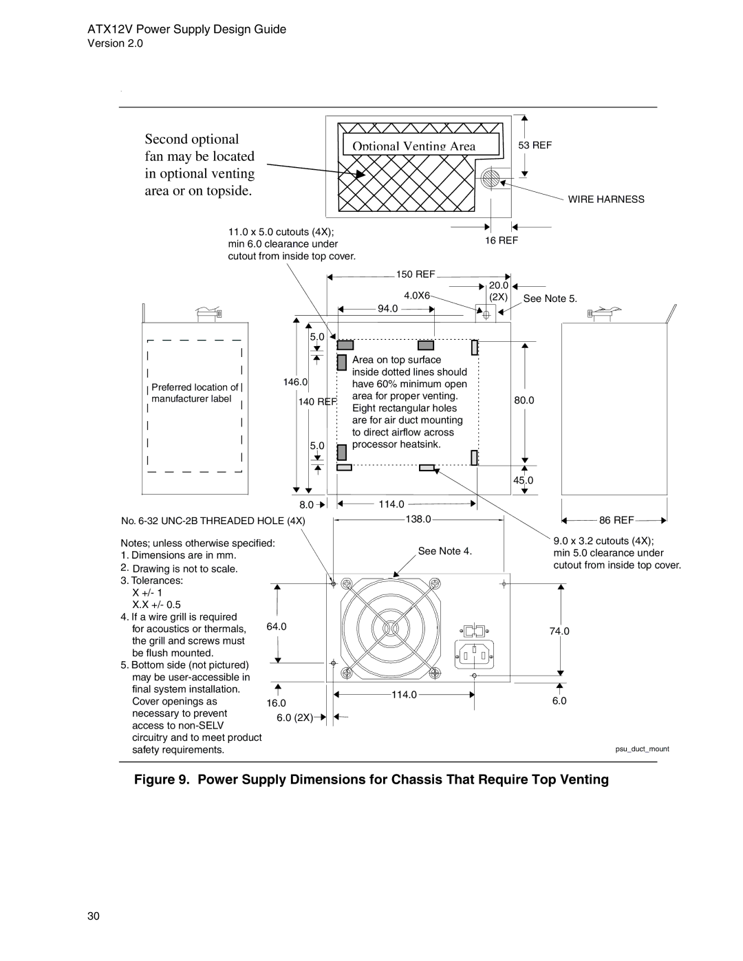
Second optional | Optional Venting Area | 53 REF | |
fan may be located | |||
|
| ||
in optional venting |
|
| |
area or on topside. |
|
|
WIRE HARNESS
11.0 x 5.0 cutouts (4X);
min 6.0 clearance under16 REF cutout from inside top cover.
|
| 150 REF | 20.0 | |
|
| 4.0X6 | ||
|
| (2X) See Note 5. | ||
|
| 94.0 |
| |
| 5.0 |
|
| |
|
| Area on top surface |
| |
| 146.0 | inside dotted lines should |
| |
Preferred location of | have 60% minimum open |
| ||
| area for proper venting. |
| ||
manufacturer label | 140 REF | 80.0 | ||
Eight rectangular holes | ||||
|
|
| ||
|
| are for air duct mounting |
| |
|
| to direct airflow across |
| |
| 5.0 | processor heatsink. |
| |
|
|
| 45.0 | |
| 8.0 | 114.0 |
| |
No. | 138.0 | 86 REF | ||
Notes; unless otherwise specified: | See Note 4. | 9.0 x 3.2 cutouts (4X); | ||
1. Dimensions are in mm. |
| min 5.0 clearance under | ||
2. Drawing is not to scale. |
|
| cutout from inside top cover. | |
3. Tolerances: |
|
|
| |
X +/- 1 |
|
|
| |
X.X +/- 0.5 |
|
|
| |
4. If a wire grill is required | 64.0 |
|
| |
for acoustics or thermals, |
| 74.0 | ||
the grill and screws must |
|
|
| |
be flush mounted. |
|
|
| |
5. Bottom side (not pictured) |
|
|
| |
may be |
|
|
| |
final system installation. |
| 114.0 | 6.0 | |
Cover openings as | 16.0 | |||
| ||||
necessary to prevent | 6.0 (2X) |
|
| |
access to |
|
| ||
|
|
| ||
circuitry and to meet product |
|
|
| |
safety requirements. |
|
| psu_duct_mount | |
Figure 9. Power Supply Dimensions for Chassis That Require Top Venting
30