Manuals
/
Intel
/
Computer Equipment
/
Computer Hardware
Intel
AX965Q
user manual
Block Diagram
Models:
AX965Q
1
10
81
81
Download
81 pages
24.11 Kb
7
8
9
10
11
12
13
14
Specs
Install
Block Diagram
Signal Signal Description
Password
Load Fail-Safe Defaults
Watch Dog Timer Select
Memory Configurations
Reset Button 2-pin Reset
Bios setup2
Page 10
Image 10
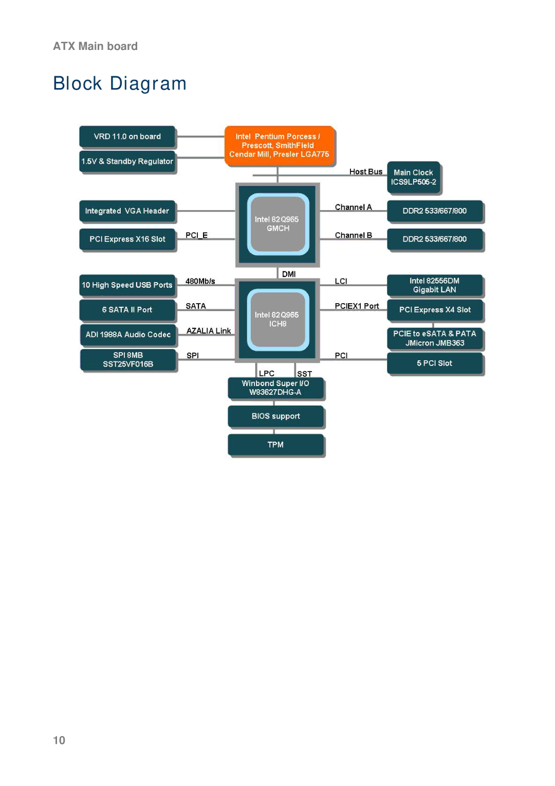
ATX Main board
Block Diagram
10
Page 9
Page 11
Page 10
Image 10
Page 9
Page 11
Contents
AX965Q User’s Manual
Ver
Contents
User’s Manual
Safety Information
Technical Support
Packing List
Revision History
Specifications Summary
Hmdi
Block Diagram
Product1 introduction
Production Introduction
Before you Proceed
Motherboard Overview
Placement Direction
Screw Holes
Motherboard Layout
Layout Content List
Label Function
Internal Connector
Central Processing Unit CPU
Installing the CPU
User’s Manual
Installing the CPU Heatsink and Fan
User’s Manual
Uninstalling the CPU Heatsink and Fan
User’s Manual
System Memory
Dimm Sockets Location
Memory Configurations
32-bit 64-bit
Qualified Vendors Lists QVL - DDR2-800MHz Capability
Size Vender Chip. No Dimm support
Qualified Vendors Lists QVL - DDR2-667MHz Capability
AM4B5708GQJS7E AU512E667C5KBGC
Qualified Vendors Lists QVL - DDR2-553MHz Capability
Kingston 5YDIID9GCT
Installing a Dimm
Removing a Dimm
Configuring an Expansion Card
Installing an Expansion Card
Expansion Slots
Standard Interrupt Assignments
IRQ
PCI Express X16 Slot
PCI Slots
PCI Express X4 Slot
Jumpers
Clear RTC RAM Clrtc
Keyboard Power Kbpwr
Connectors
Rear Panel Connectors
Headset Port Channel
PS/2 KB connector This port is for a PS/2 keyboard
Internal Connectors Front Panel Audio Connector Aafp
ATX Power Connector ATX12V, Eatxpwr
Important notes on the Motherboard Power Requirements
Optical Drive Audio Connector CD
CPU & Chassis Fan Connector CPUFAN, CHAFAN1, CHAFAN2
ATX Main board
User’s Manual
ATX Power Button/Soft-off Button 2-pin Pwrsw
System Panel Connector Fpanel
System Power LED 2-pin Pwrled
Reset Button 2-pin Reset
Signal Signal Description
Primary Eide Connector Prieide
Drive jumper setting Mode of devices Cable connector
Digital Audio Connector Spdifout
Serial ATA RAID Connector SATARAID1
USB 2.0 Connector USB56, 78
Trusted Platform Module TPM Connector TPMSLOT1
Bios setup2
Bios Setup
Bios Setup Program
List Box
Sub-menu
Bios Menu Screen
Date Day, xx/xx/xxxx
Standard Cmos Features
IDE Device Setup
Time
Halt On
Driver A/B
Video
Memory
Advanced Bios Features
CPU Features
Quick Power On Self Test
CPU L1 & L2 & L3 Cache
Boot Up Floppy Seek
First / Second / Third Boot Device
Boot Other Device
Swap Floppy Drive
Gate A20 Option
Boot Up NumLock Status
Typematic Rate Setting
Typematic Rate Chars/Sec
OS Select for Dram 64MB
Apic Mode
MPS Version Control for OS
Small Logo EPA Show
System Bios Cacheable
Advanced Chipset Features
Memory Hole at 15M-16M
On-Chip Frame Buffer Size
Dvmt Mode
PCI Express Root Port Function 3.4 PEG/Onchip VGA Control
DVMT/FIXED Memory Size
Integrated Peripherals OnChip IDE Device
Super I/O Device
Watch Dog Timer Select
USB Device Setting
Acpi Function
Power Management Setup
Run Vgabios if S3 Resume
Acpi Suspend Type
Video Off Method
Power Management
Suspend Mode
Video Off In Suspend
Resume by Alarm
HDD Power Down
Power On by Ring
Soft-off by PWR-BTTN
Rest Configuration Data
6 PnP/PCI Configurations Init Display First
Resource Controlled By
Maximum Payload Size
Auto Detect PCI Clk
Frequency/Voltage Control
CPU Clock Ratio
Spread Spectrum
Load Fail-Safe Defaults
Load Optimized Defaults
Set Supervisor/User Password
Please Confirm Your Password
Save and Exit Setup
Exit Without Saving
Top
Page
Image
Contents