Manuals
/
Intel
/
Computer Equipment
/
Computer Hardware
Intel
AX965Q user manual Power Fan Connector PWRFAN, Serial Port Connector 1 COM1, ATX Main board
Models:
AX965Q
1
44
81
81
Download
81 pages
24.11 Kb
41
42
43
44
45
46
47
48
<
>
Specifications
Install
Block Diagram
Placement Direction
Memory Configurations
z Reset Button 2-pin RESET
BIOS setup2
Push down two fasteners at a time in a diagonal sequence to secure the heatsink and fan assembly in place
+5V Default +5VSB
Watch Dog Timer Select
Page 44
Image 44
ATX Main board
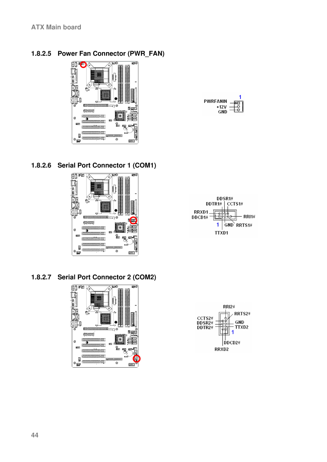
1.8.2.5 Power Fan Connector (PWR_FAN)
1.8.2.6 Serial Port Connector 1 (COM1)
1.8.2.7 Serial Port Connector 2 (COM2)
44
Page 43
Page 45
Page 44
Image 44
Page 43
Page 45
Contents
AX965Q User’s Manual
Contents
Safety Information
Specifications Summary
Block Diagram
User’s Manual
Contents
BIOS Setup
ATX Main board
Safety Information
Electrical safety
Operation safety
ATX Main board
Technical Support
Conventions Used in This Guide
User’s Manual
ATX Main board
Packing List
ATX Main board
Revision History
Revision
Revision History
Date
Specifications Summary
4 x COM, 10 x USB 2.0, 5 x SATA or 7 x SATA connectors for ICH8DO
ATX Main board
System
Specifications Summary
User’s Manual
ATX Main board
Display
Block Diagram
ATX Main board
Product1 introduction
User’s Manual
it supports
ATX Main board
Production Introduction
1.1 Before you Proceed
Onboard LED
ATX Main board
1.2.1 Placement Direction
1.2 Motherboard Overview
1.2.2 Screw Holes
User’s Manual
1.3 Motherboard Layout
ATX Main board
1.3.1 Layout Content List
Rear Panel Connector
Slots
Label
Internal Connector
Reserved
Manufacture use only
Optional for ICH8DO
ATX Main board
1.4 Central Processing Unit CPU
User’s Manual
1.4.1 Installing the CPU
ATX Main board
ATX Main board
User’s Manual
4. Lift the load plate with your thumb and forefinger to a 100º angle A, then push the PnP cap from the load plate window to remove B
1.4.2 Installing the CPU Heatsink and Fan
ATX Main board
ATX Main board
2. Push down two fasteners at a time in a diagonal sequence to secure the heatsink and fan assembly in place
User’s Manual
1.4.3 Uninstalling the CPU Heatsink and Fan
1. Disconnect the CPU fan cable from the connector on the motherboard
ATX Main board
2. Rotate each fastener counterclockwise
ATX Main board
5. Rotate each fastener clockwise to ensure correct orientation when reinstalling
User’s Manual
1.5 System Memory
1.5.1 DIMM Sockets Location
Channel
Socket
1.5.2 Memory Configurations
Notes on memory limitations
User’s Manual
32-bit
1.5.2.1 Qualified Vendors Lists QVL - DDR2-800MHz Capability
Size
Vender
Chip. No
1.5.2.2 Qualified Vendors Lists QVL - DDR2-667MHz Capability
User’s Manual
Size
Vender
ATX Main board
Size
Vender
Chip. No
1.5.2.3 Qualified Vendors Lists QVL - DDR2-553MHz Capability
User’s Manual
Size
Vender
1.5.3 Installing a DIMM
ATX Main board
1.5.4 Removing a DIMM
User’s Manual
2. Remove the DIMM from the socket
ATX Main board
1.6.1 Installing an Expansion Card
1.6.2 Configuring an Expansion Card
1.6 Expansion Slots
ATX Main board
1.6.3 Standard Interrupt Assignments
Priority
Standard Function
User’s Manual
1.6.4 PCI Slots
1.6.5 PCI Express X16 Slot
1.6.6 PCI Express X4 Slot
ATX Main board
1.7 Jumpers
1.7.1 Clear RTC RAM CLRTC
User’s Manual
ATX Main board
ATX Main board
1.7.2 Keyboard Power KBPWR
+5V Default +5VSB
1.8 Connectors
1.8.1 Rear Panel Connectors
Description
ACT / LINK LED
Headset
Port
2-channel
6-channel
User’s Manual
Label
Function
Description
1.8.2 Internal Connectors 1.8.2.1 Front Panel Audio Connector AAFP
ATX Main board
1.8.2.2 ATX Power Connector ATX12V, EATXPWR
Important notes on the Motherboard Power Requirements
User’s Manual
ATX Main board
1.8.2.3 Optical Drive Audio Connector CD
ATX Main board
1.8.2.4 CPU & Chassis Fan Connector CPUFAN, CHAFAN1, CHAFAN2
User’s Manual
ATX Main board
CHAFAN1 CHAFAN2 CPUFAN
1.8.2.5 Power Fan Connector PWRFAN
1.8.2.6 Serial Port Connector 1 COM1
1.8.2.7 Serial Port Connector 2 COM2
ATX Main board
1.8.2.8 Serial Port Connector 3 COM3
1.8.2.9 Serial Port Connector 4 COM4
1.8.2.10 Floppy Disk Drive Connector FLOPPY
User’s Manual
1.8.2.11 System Panel Connector FPANEL
z System Power LED 2-pin PWRLED
z ATX Power Button/Soft-off Button 2-pin PWRSW
z Reset Button 2-pin RESET
1.8.2.12 IEEE 1394a Connector IE13942, Optional
1.8.2.13 IrDA Connector IRCON1 z Signal Description
Signal
Signal Description
1.8.2.14 Primary EIDE Connector PRIEIDE
Drive jumper setting
Mode of devices
Cable connector
ATX Main board
1.8.2.16 Digital Audio Connector SPDIFOUT
User’s Manual
1.8.2.17 Serial ATA RAID Connector SATARAID1
ATX Main board
ATX Main board
1.8.2.18 USB 2.0 Connector USB56, 78
User’s Manual
1.8.2.19 Trusted Platform Module TPM Connector TPMSLOT1
ATX Main board
BIOS setup2
This chapter tells how to change
of the BIOS parameters are also provided
User’s Manual
ATX Main board
BIOS Setup
2.1 BIOS Setup Program
2.1.1 Legend Box
Keys
Function Description
2.1.2 List Box
2.2 BIOS Menu Screen
ATX Main board
2.2.1 Standard CMOS Features
z IDE Device Setup
2.2.1.1 Date Day, xx/xx/xxxx
2.2.1.2 Time
2.2.1.4 Driver A/B
2.2.1.5 Video
2.2.1.6 Halt On
2.2.1.7 Memory
ATX Main board
2.2.2 Advanced BIOS Features
User’s Manual
2.2.2.1 CPU Features
ATX Main board
2.2.2.5 Quick Power On Self Test
2.2.2.4 CPU L1 & L2 & L3 Cache
User’s Manual
ATX Main board
2.2.2.6 First / Second / Third Boot Device
2.2.2.7 Boot Other Device
2.2.2.9 Boot Up Floppy Seek
2.2.2.8 Swap Floppy Drive
2.2.2.10 Boot Up NumLock Status
2.2.2.12 Typematic Rate Setting
2.2.2.11 Gate A20 Option
2.2.2.13 Typematic Rate Chars/Sec
2.2.2.16 APIC Mode
2.2.2.17 MPS Version Control for OS
2.2.2.18 OS Select for DRAM 64MB
2.2.2.19 Small Logo EPA Show
2.2.3 Advanced Chipset Features
2.2.3.1 System BIOS Cacheable
2.2.3.2 Memory Hole at 15M-16M
User’s Manual
2.2.3.6 DVMT Mode
2.2.3.3 PCI Express Root Port Function 2.2.3.4 PEG/Onchip VGA Control
2.2.3.5 On-Chip Frame Buffer Size
2.2.3.7 DVMT/FIXED Memory Size
ATX Main board
2.2.4 Integrated Peripherals 2.2.4.1 OnChip IDE Device
User’s Manual
2.2.4.2 Super I/O Device
ATX Main board
ATX Main board
2.2.4.3 Watch Dog Timer Select
User’s Manual
2.2.4.4 USB Device Setting
ATX Main board
2.2.5 Power Management Setup
2.2.5.3 Run VGABIOS if S3 Resume
2.2.5.1 ACPI Function
2.2.5.2 ACPI Suspend Type
2.2.5.4 Power Management
2.2.5.9 Suspend Mode
2.2.5.5 Video Off Method
2.2.5.6 Video Off In Suspend
2.2.5.10 HDD Power Down
2.2.5.13 Power On by Ring
2.2.5.15 Resume by Alarm
2.2.5.11 Soft-off by PWR-BTTN
2.2.6 PnP/PCI Configurations 2.2.6.1 Init Display First
2.2.6.2 Rest Configuration Data
2.2.6.3 Resource Controlled By
ATX Main board
ATX Main board
2.2.6.6 Maximum Payload Size
User’s Manual
2.2.7 Frequency/Voltage Control
2.2.7.2 CPU Clock Ratio
2.2.7.3 Auto Detect PCI Clk
2.2.7.4 Spread Spectrum
ATX Main board
2.2.8 Load Fail-Safe Defaults
User’s Manual
2.2.9 Load Optimized Defaults
ATX Main board
2.2.10 Set Supervisor/User Password
Please Confirm Your Password
User’s Manual
ATX Main board
2.2.11 Save and Exit Setup
ATX Main board
ATX Main board
2.2.12 Exit Without Saving
User’s Manual