ATX Main board
1.8.2.14 Primary EIDE Connector (PRI_EIDE)
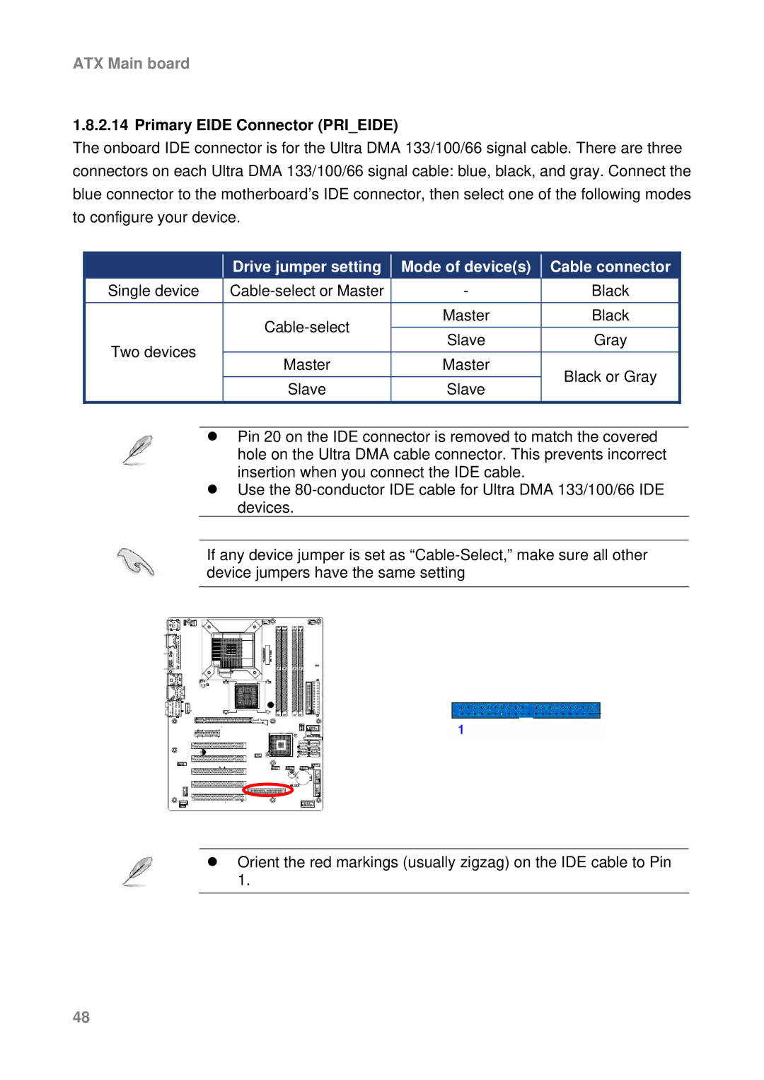
The onboard IDE connector is for the Ultra DMA 133/100/66 signal cable. There are three connectors on each Ultra DMA 133/100/66 signal cable: blue, black, and gray. Connect the blue connector to the motherboard’s IDE connector, then select one of the following modes to configure your device.
|
| Drive jumper setting |
| Mode of device(s) |
| Cable connector |
Single device |
|
| - |
| Black | |
|
|
| Master |
| Black | |
Two devices |
|
| Slave |
| Gray | |
|
|
|
| |||
|
|
|
|
|
| |
| Master |
| Master |
| Black or Gray | |
|
|
|
| |||
|
|
|
|
|
| |
|
| Slave |
| Slave |
| |
|
|
|
|
| ||
|
|
|
|
|
|
|
zPin 20 on the IDE connector is removed to match the covered hole on the Ultra DMA cable connector. This prevents incorrect insertion when you connect the IDE cable.
zUse the
If any device jumper is set as
zOrient the red markings (usually zigzag) on the IDE cable to Pin 1.
48