Manuals
/
Intel
/
Computer Equipment
/
Computer Hardware
Intel
GA-8IPXDR-E CLRCMOS Clear CMOS Function, 1 1-2 close Clear CMOS 1 2-3 close Normal Default
Models:
GA-8IPXDR-E
1
35
70
70
Download
70 pages
37.18 Kb
32
33
34
35
36
37
38
39
<
>
Install
GA-8IPXDR-E System Block Diagram
Advanced Configuration Chipset Configuration
Connect ribbon cables, cabinet wires, and power supply
` Reset Case Open Status
BIOS Setup
close VGA Enabled Default
1 +5VSB 2 GND 3 Signal
D BT1 Battery
3 Jumper Setting Introduction
Page 35
Image 35
Jumper Setting
15) CLR_CMOS (Clear CMOS Function)
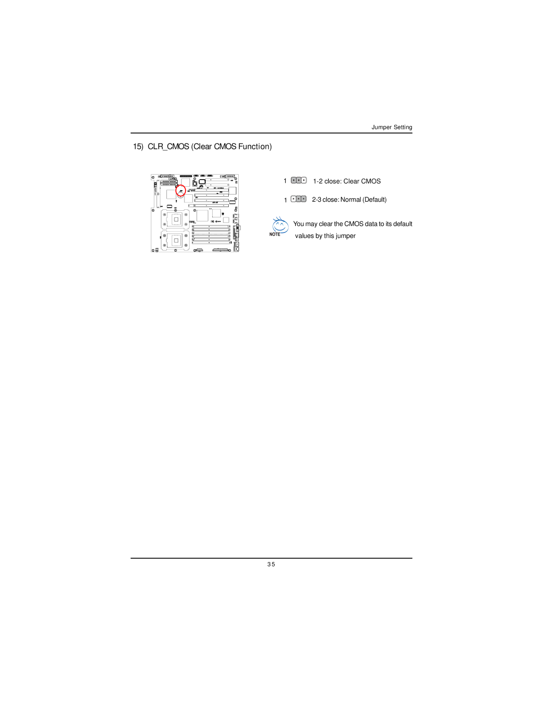
1
1-2
close: Clear CMOS
1
2-3
close: Normal (Default)
You may clear the CMOS data to its default values by this jumper
3 5
Page 34
Page 36
Page 35
Image 35
Page 34
Page 36
Contents
Intel Dual XeonTM Serverboard
USER’S MANUAL
GA-8IPXDR-E Series
Table of Content
Chapter 5 Appendix
GA-8IPXDR-E System Block Diagram
Chapter 4 Technical Reference
3 GA-8IPXDR-EC Supports 533MHz / without SCSI function
Item Checklist
GA-8IPXDR-E Series Model List
3 GA-8IPXDR-E Supports 533MHz / with SCSI function
Installing the motherboard to the chassis…
Chapter 1 Introduction
Features Summary
Hardware Monitor
Note that * indicates for GA-8IPXDR-E Only
GA-8IPXDR-EC Motherboard Layout
Step1 Step
Chapter 2 Hardware Installation Process
Step
Step Step
Step3 Fit the 4 screws with 2 CPU retention modules on the chassis
Step 1 Install the Central Processing Unit CPU
Step 1-1 Installing Motherboard to the Chassis
For socket 603 / 400MHz
Step 1-2 CPU Installation
Pin1 indicator
Socket Actuation Lever
For socket 604 / 533MHz
0 Please make sure the CPU type is supported by the motherboard
Pin1 indicator
4. Completive picture for first step
Step 1-3 CPU Heat Sink Installation
1. Use qualified fan approved by Intel
3. First step of assembling
0 Please use Intel approved cooling fan
Registered DDR
Step 2 Install memory modules
J6 B-3 J3 A-3
Installation Step
Step 3 Install expansion cards
Step 4-1 I/O Back Panel Introduction
Step 4 Connect ribbon cables, cabinet wires, and power supply
X PS/2 Keyboard and PS/2 Mouse Connector
Y USB Connector
VGA Port
ZParallel Port / Serial Port / VGA Port LPT/COMA/VGA
\ LAN1 / LAN2 Port
Parallel Port 25 pin Female
ATX3
Step 4-2 Connectors Introduction
H G S I E F
P U T R
Pin No. Definition 1 GND 2 +12v 3 GND 4 +12V 5 GND 6 +12V 7 GND
A ATX3 2x12 Pin ATX Power
B ATX1 ATX1 Power
¾This connector ATX +12V is used only for CPU Core Voltage
¾Please note, a proper installation of the CPU
C ATX2 +12V Power Connector
O/Q J30/J32 CPU FAN Connector
by overheating.The CPU fan connector
1 GND 2 +12v/Control 3 Sense
F/O J33/J34 System FAN Connector
P J31 Power FAN Connector
Pin No
Pin No
T J18 Wake On LAN Connector
L COM 2 Connector
1 +5VSB 2 GND 3 Signal
SCSI SCSI
E/F SCSI1/2 Connector
I/J IDE1/IDE2 IDE1 / IDE2 ConnectorPrimary/Secondary
Pin No
G FDD1 Floppy Connector
M CASE OPEN
1 Signal 2 GND
Power
N J20 Front Panel Connector-- Power button and Power LED
H USB1 Front USB Connector
Power
D BT1 Battery
K IPMICON IPMI Connector
K FPANEL connector
11 JP
Step 4-3 Jumper Setting Introduction
9 JP
10 JP
1-2 close VGA Enabled Default
1 JP 1 Onboard SCSI Function
2 JP 8 Onboard VGA Functon
3 JP 9 Front Side USB Wake Up Function
Default
4 JP 10 Rear Side USB Wake Up Function
5 / 6 JP13 / JP14 P64H2#1 Primary PCI-X max Bus Frequency Function
For PCI-X1
JP18
7 / 8 JP15 / JP16 P64H2#1 Secondary PCI-X max Bus Frequency Selection
For Giagbit LAN U6
JP17
JP19
13 JP21 On Board SCSI Channel A Terminator Function
14 JP22 On Board SCSI Channel B Terminator Function
JP20
You may clear the CMOS data to its default values by this jumper
15 CLRCMOS Clear CMOS Function
1 1-2 close Clear CMOS 1 2-3 close Normal Default
CONTROLKEYS
Chapter 3 BIOS Setup
ENTERINGSETUP
z Main
Status Page Setup Menu / Option Page Setup Menu
z Boot
GETTINGHELP MainMenu
System Time
Main
System Date
TYPE
FloppyDriveA/B
IDE Primary Master, Slave / Secondary Master, Slave
This field only shows the information of Fast Programmed
SystemInformation
Enables 32 bit access to maximize the hard disk data
Advanced
Advanced
About This Section Advanced
Advanced Configuration Chipset Configuration
` Quick Boot
Advanced Configuration
AdvancedConfiguration
indicates DISPLAY ONLY
` Console Redirect
1.4 Support MPS Version 1.4 . Default Value 1.1 Support MPS Version
Disable this function.Default Value
` MPS Version for O.S
` Hyper Threading
Chipset Configuration
` ClkGen Spread Spectrum
` PME Event Wake Up
Power Management Configuration
PowerManagement Configuration
` System After AC Back
` Relaxed Ordering
PCI-X Configuration
PCI-X Configuration
` Data Parity Error Recovery
` OnBoard FDC
PeripheralConfiguration
Peripheral Configuration
` OnBoard IDE
` OnBoard Parallel Port
` OnBoard Serial Port A
` OnBoard Serial Port B
` Parallel Port IRQ
` Parallel Port Mode
Normal
Bi-Directional
` OnBoard SCSI
Enables onboard Gigabit LANs. Default Value
Enable onboard SCSI. Default Value
` OnBoard Gigabit LANs
VCC2.5
Advanced
indicates DISPLAY ONLY
VCC1.8
` CPU Vlotage Fail Alarm
HardwareMonitorConfiguration
` Reset Case Open Status
` CPU Fan Fail Alarm
` System FAN
` Power FAN 1/2
` CPU 0 / 1 FAN
Security
Set Supervisor Password
Security
About This Section Security
Password Check
Set User Password
` 1st / 2nd / 3 rd Boot Device
Boot
About This Section Boot
Boot Device Priority
Disable this function. Default Value
` OnBoard LAN Boot ROM
` The Choice for 1st Boot Device , Removable Device Default Value
Enable OnBoard LAN Boot ROM
About This Section Security
Exit Saving Changes Exit Discarding Changes Load Default Settings
Exit
Load Original Values
Load Default Settings
Exit Saving Changes
Exit Discarding Changes
Chapter 4 Technical Reference
GA-8IPXDR-E System Block Diagram
Note Driver CD Ver
Appendix A Intel Network Driver Installation
Chapter 5 Appendix
Startinginstallation
Appendix
Appendix B INF Update Installation Driver for chipset
3.Click Yes at License Agreement window
Appendix C ATI Rage XL VGA Driver Installation
2.Click Next 1.Click ATI Rage XL VGA Driver item
1. Click Adaptec SCSI Driver item
Appexdix D Adaptec SCSI Driver Installation
Http//networking.gigabyte.com.tw
Appendix E Utilites Installation
Appendix F About Updateing Latest version of BIOS
Norton Internet Security
Appendix G IPMI Connector Pin Definition
Appendix H Acronyms
Local Area Network
Other Device
Technical Support/RMA Sheet
Power supply
Contact Person