Manuals
/
Intel
/
Computer Equipment
/
Computer Hardware
Intel
GA-8IPXDR-E
user manual
Technical Reference
Models:
GA-8IPXDR-E
1
60
70
70
Download
70 pages
37.18 Kb
57
58
59
60
61
62
63
64
Install
Password
Default
AdvancedConfiguration
Bios Setup
USB Connector
Bios
BT1 Battery
Jumper Setting Introduction
Checklist
Page 60
Image 60
GA-8IPXDR
Motherboard
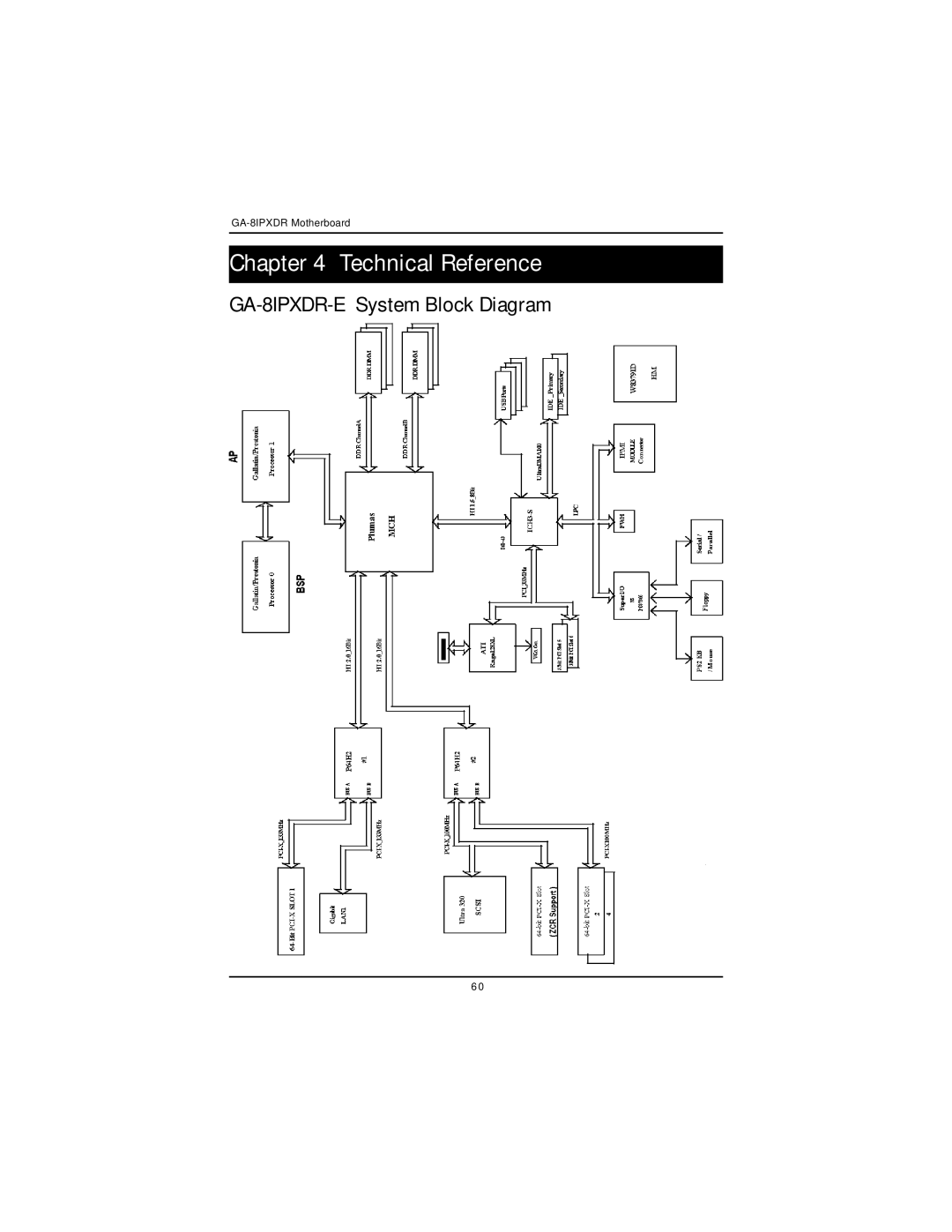
Chapter 4 Technical Reference
GA-8IPXDR-E
System Block Diagram
6 0
Page 59
Page 61
Page 60
Image 60
Page 59
Page 61
Contents
USER’S Manual
Table of Content
Technical Reference
Item Checklist
Installing the motherboard to the chassis…
Introduction
Bios
GA-8IPXDR-EC Motherboard Layout
Hardware Installation Process
Step
Install the Central Processing Unit CPU
Installing Motherboard to the Chassis
CPU Installation
For socket 603 / 400MHz
For socket 604 / 533MHz
CPU Heat Sink Installation
GA-8IPXDR-EC Motherboard
Install memory modules
Installation Step
Install expansion cards
PS/2 Keyboard and PS/2 Mouse Connector
USB Connector
I/O Back Panel Introduction
ZParallel Port / Serial Port / VGA Port LPT/COMA/VGA
\ LAN1 / LAN2 Port
Connectors Introduction
ATX3 2x12 Pin ATX Power
ATX1 ATX1 Power
ATX2 +12V Power Connector
J30/J32 CPU FAN Connector
J33/J34 System FAN Connector
J31 Power FAN Connector
J18 Wake On LAN Connector
COM 2 Connector
SCSI1/2 Connector
IDE1/IDE2 IDE1 / IDE2 ConnectorPrimary/Secondary
FDD1 Floppy Connector
Case Open
J20 Front Panel Connector-- Power button and Power LED
USB1 Front USB Connector
Ipmicon Ipmi Connector
BT1 Battery
Fpanel connector
JPSPK+ JPHD+ Jprst Jphd Jpspk
Jumper Setting Introduction
JP 1 Onboard Scsi Function JP 8 Onboard VGA Functon
JP 9 Front Side USB Wake Up Function
Default
JP 10 Rear Side USB Wake Up Function
JP17 JP18
13 JP21 On Board Scsi Channel a Terminator Function
14 JP22 On Board Scsi Channel B Terminator Function
Clrcmos Clear Cmos Function
Bios Setup
Status Page Setup Menu / Option Page Setup Menu
Boot
MainMenu
Main
System Date
System Time
FloppyDriveA/B
IDE Primary Master, Slave / Secondary Master, Slave
SystemInformation
Advanced
About This Section Advanced
AdvancedConfiguration
` Quick Boot
Indicates Display only
` MPS Version for O.S
` Console Redirect
Chipset Configuration
` ClkGen Spread Spectrum
` Hyper Threading
PowerManagement Configuration
` System After AC Back
` PME Event Wake Up
PCI-X Configuration
` Data Parity Error Recovery
` Relaxed Ordering
Peripheral Configuration
` OnBoard IDE
` OnBoard FDC
` OnBoard Serial Port a
` OnBoard Serial Port B
` OnBoard Parallel Port
` Parallel Port Mode
Normal
Bi-Directional
` Parallel Port IRQ
` OnBoard Gigabit LANs
` OnBoard Scsi
CPU0 FAN RPM CPU1 FAN
HardwareMonitorConfiguration
` Power FAN 1/2
` CPU 0 / 1 FAN
` System FAN
Set Supervisor Password
About This Section Security
Set User Password
Password Check
About This Section Boot
Boot Device Priority
` 1st / 2nd / 3 rd Boot Device
` OnBoard LAN Boot ROM
Exit
Load Default Settings
Exit Saving Changes
Exit Discarding Changes
Load Original Values
Technical Reference
Appendix a Intel Network Driver Installation
Appendix
GA-8IPXDR-EC Motherboard
Appendix B INF Update Installation Driver for chipset
Appendix C ATI Rage XL VGA Driver Installation
Appexdix D Adaptec Scsi Driver Installation
Appendix E Utilites Installation
Appendix F About Updateing Latest version of Bios
Http//networking.gigabyte.com.tw
Appendix G Ipmi Connector Pin Definition
Appendix H Acronyms
LAN
Technical Support/RMA Sheet
Top
Page
Image
Contents