INSTALLATIONS
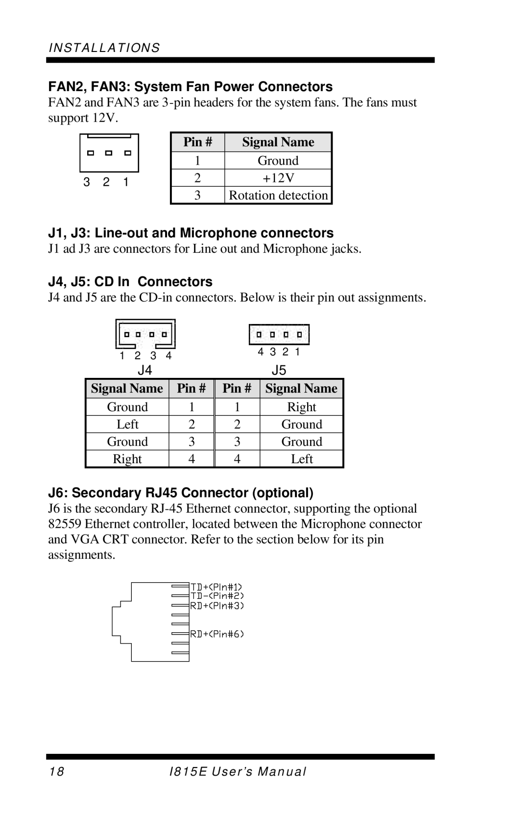
FAN2, FAN3: System Fan Power Connectors
FAN2 and FAN3 are
3 2 1
Pin # | Signal Name |
|
|
1Ground
2+12V
3Rotation detection
J1, J3: Line-out and Microphone connectors
J1 ad J3 are connectors for Line out and Microphone jacks.
J4, J5: CD In Connectors
J4 and J5 are the
1 | 2 | 3 | 4 | 4 | 3 | 2 | 1 | ||
|
|
|
|
| |||||
| J4 |
|
|
|
| J5 |
| ||
Signal Name |
| Pin # | Pin # |
| Signal Name | ||||
Ground |
|
| 1 | 1 |
|
| Right | ||
Left |
|
| 2 | 2 |
|
| Ground | ||
Ground |
|
| 3 | 3 |
|
| Ground | ||
Right |
|
| 4 | 4 |
|
|
| Left | |
J6: Secondary RJ45 Connector (optional)
J6 is the secondary
18 | I815E User’s Manual |