INSTALLATIONS
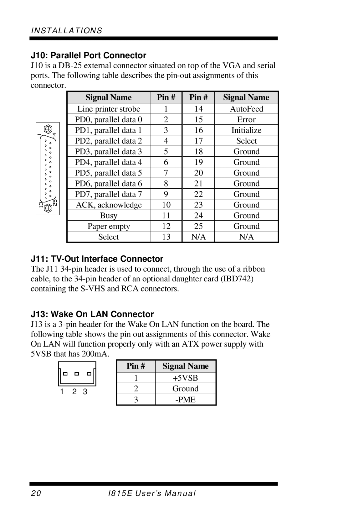
J10: Parallel Port Connector
J10 is a
| Signal Name | Pin # | Pin # | Signal Name |
| Line printer strobe | 1 | 14 | AutoFeed |
| PD0, parallel data 0 | 2 | 15 | Error |
| PD1, parallel data 1 | 3 | 16 | Initialize |
| PD2, parallel data 2 | 4 | 17 | Select |
| PD3, parallel data 3 | 5 | 18 | Ground |
| PD4, parallel data 4 | 6 | 19 | Ground |
| PD5, parallel data 5 | 7 | 20 | Ground |
| PD6, parallel data 6 | 8 | 21 | Ground |
| PD7, parallel data 7 | 9 | 22 | Ground |
| ACK, acknowledge | 10 | 23 | Ground |
| Busy | 11 | 24 | Ground |
| Paper empty | 12 | 25 | Ground |
| Select | 13 | N/A | N/A |
J11: TV-Out Interface Connector
The J11
J13: Wake On LAN Connector
J13 is a
1 2 3
Pin # | Signal Name |
1+5VSB
2Ground
3
20 | I815E User’s Manual |