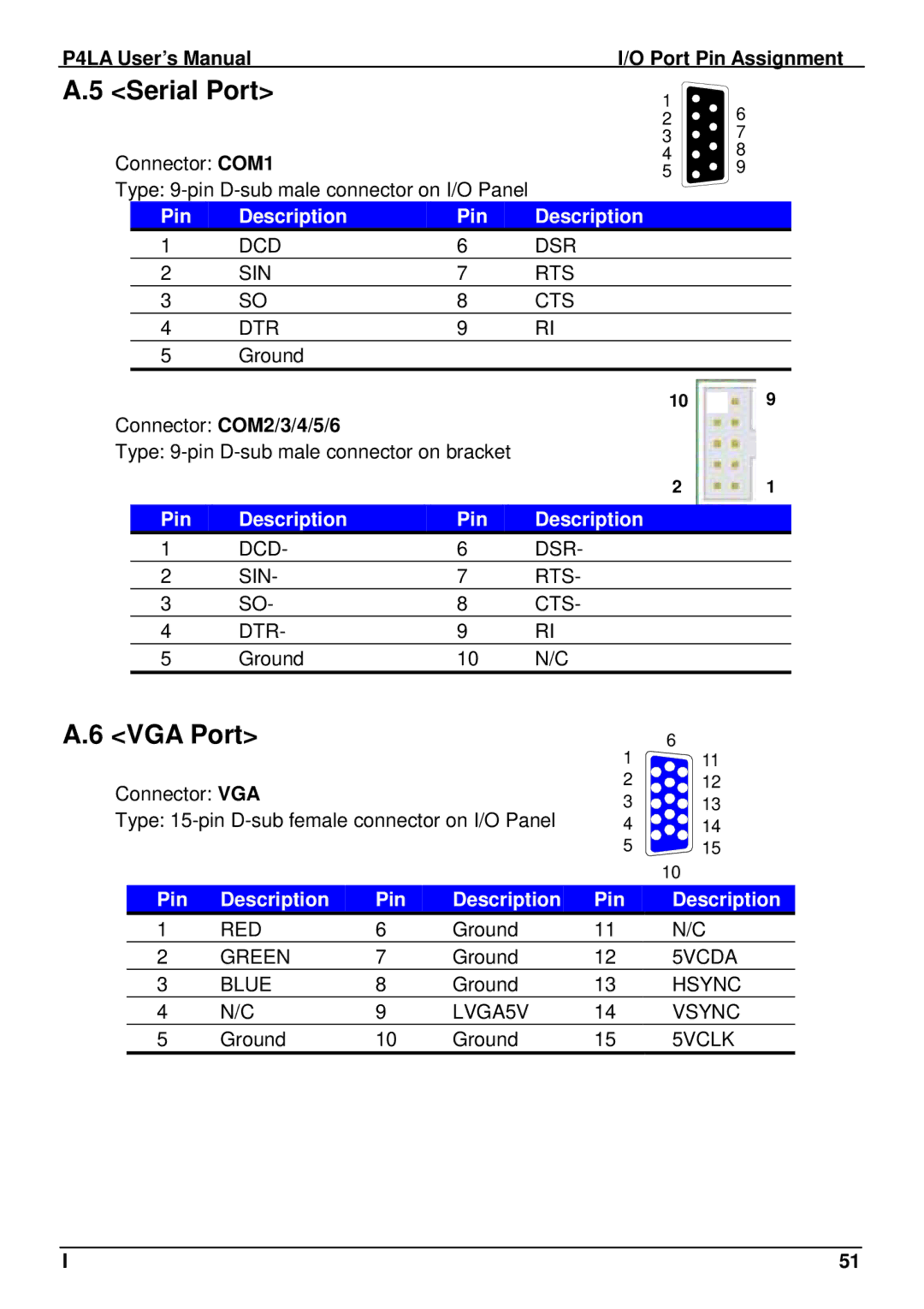
P4LA specifications
The Intel P4LA is a notable processor in the realm of computing, particularly with regard to performance and versatility. As part of Intel's Pentium 4 lineup, it offers a unique blend of features and characteristics aimed at enhancing computing efficiency and user experience.One of the key features of the P4LA is its architecture, which is based on the NetBurst microarchitecture. This technology utilizes a high clock speed and a wide execution pipeline, allowing the processor to handle multiple instructions simultaneously. The NetBurst architecture enables the P4LA to achieve impressive single-threaded performance, making it an excellent choice for applications that rely heavily on a single core's capabilities.
The Intel P4LA also introduces Hyper-Threading technology, which allows the processor to simulate two logical processors. This capability significantly improves multitasking performance by allowing the operating system to schedule multiple threads on the same core. Users can experience smoother performance while running multiple applications, which is a considerable advantage in today's multitasking environment.
In terms of manufacturing technology, the Intel P4LA is built on a 90nm process. This smaller process node allows for higher transistor density, resulting in improved power efficiency and performance. The 90nm technology also contributes to lower heat output, which is a critical factor for maintaining system stability and reliability.
Another defining characteristic of the P4LA is its integrated Intel 865G chipset support, which enhances overall system performance by providing features like dual-channel DDR memory support. This allows for higher memory bandwidth, which is essential for data-intensive applications such as video editing and gaming.
The P4LA's compatibility with various socket types, including Socket 478, ensures it can be utilized in a wide range of motherboards, providing flexibility for system builders and upgrade enthusiasts. The processor's thermal design power (TDP) typically ranges around 60 watts, striking a balance between performance and thermal output.
In conclusion, the Intel P4LA stands as a powerful processor that encapsulates the strengths of the Pentium 4 series. With its advanced architecture, support for Hyper-Threading technology, and efficient manufacturing process, the P4LA delivers robust performance for both everyday computing tasks and demanding applications. Whether used in home PCs, workstations, or gaming rigs, the P4LA continues to be a noteworthy player in the world of processors.

