7.Line up the alignment marks on the processor and the socket, and insert the processor into the socket.
Note: Make sure the alignment triangle mark and the alignment triangle cutout align correctly.
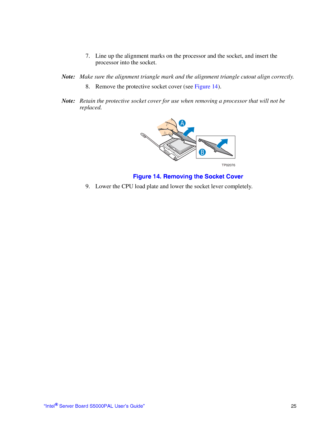
8. Remove the protective socket cover (see Figure 14).
Note: Retain the protective socket cover for use when removing a processor that will not be replaced.
A
B |
TP02076 |
Figure 14. Removing the Socket Cover
9. Lower the CPU load plate and lower the socket lever completely.
“Intel® Server Board S5000PAL User’s Guide” | 25 |
