Memory
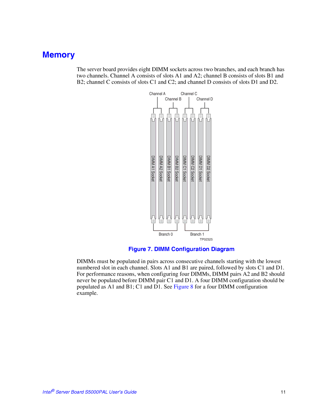
The server board provides eight DIMM sockets across two branches, and each branch has two channels. Channel A consists of slots A1 and A2; channel B consists of slots B1 and B2; channel C consists of slots C1 and C2; and channel D consists of slots D1 and D2.
Channel A | Channel C |
Channel B
Channel D
DIMM A1 Socket
DIMM A2 Socket
DIMM B1 Socket
DIMM B2 Socket
DIMM C1 Socket
DIMM C2 Socket
DIMM D1 Socket
DIMM D2 Socket
Branch 0 | Branch 1 |
| TP02325 |
Figure 7. DIMM Configuration Diagram
DIMMs must be populated in pairs across consecutive channels starting with the lowest numbered slot in each channel. Slots A1 and B1 are paired, followed by slots C1 and D1. For performance reasons, when configuring four DIMMs, DIMM pairs A2 and B2 should never be populated before DIMM pair C1 and D1. A four DIMM configuration should be populated as A1 and B1; C1 and D1. See Figure 8 for a four DIMM configuration example.
Intel® Server Board S5000PAL User’s Guide | 11 |
