PROCEDURE 5 | WHEEL LOCK |
W
H
E
E
L
L O C K
This procedure includes the following:
Installing CLD on Existing Wheelchair Replacing the CLD Wheel Lock Installing/Removing CLD Wheel Lock Adjusting Wheel Lock Assembly Position Adjusting Wheel Lock Engagement Position
WARNING
After ANY adjustments, repair or service and BE- FORE use, make sure all attaching hardware is tightened securely - otherwise injury or damage may result.
INSTALLING CLD ON EXISTING WHEELCHAIR
1.Adjusting the wheel lock assembly position. Refer to
ADJUSTING WHEEL LOCK ASSEMBLY POSI- TION in this procedure of the manual.
2.Adjust the wheel lock engagement position. Refer to ADJUSTING WHEEL LOCK ENGAGEMENT POSITION in this procedure of the manual.
REPLACING THE CLD WHEEL LOCK
ADJUSTING WHEEL LOCK ASSEMBLY POSITION (FIGURE 2)
NOTE: If wheels are pneumatic, before adjusting the wheel lock, ensure that the tires are inflated to the rec- ommended psi located on the side wall of the tire.
1.Refer to the chart on this page to determine the mount- ing position of the two (2) flat screws securing the wheel lock adjustment rod to the wheel lock support bracket.
2.Secure wheel lock adjustment rod to the wheel lock support bracket with the two (2) flat screws. Tighten securely.
FRONT VIEW OF TRANSMISSION SUPPORT
BRACKET
Wheelchairs Built BEFORE 09/05/00
A B C
Wheel
Lock
Support
MountingBracket
Holes
1.Remove the EXISTING CLD wheel lock. Refer to
INSTALLING/REMOVING THE CLD WHEEL LOCK in this procedure of the manual.
2.Install the NEW CLD wheel lock. Refer to INSTALL- ING/REMOVING THE CLD WHEEL LOCK in this procedure of the manual.
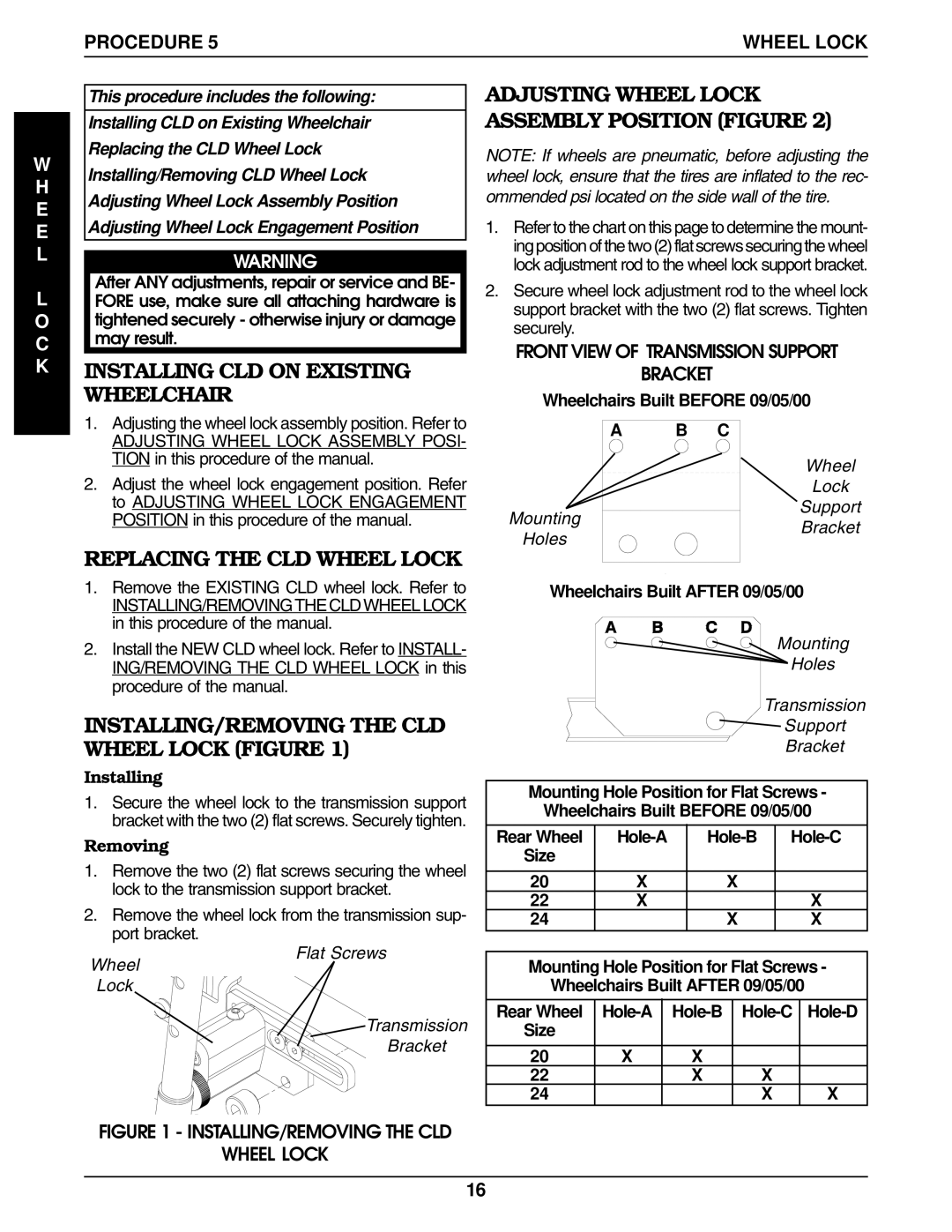
INSTALLING/REMOVING THE CLD WHEEL LOCK (FIGURE 1)
Installing
1.Secure the wheel lock to the transmission support bracket with the two (2) flat screws. Securely tighten.
Removing
1.Remove the two (2) flat screws securing the wheel lock to the transmission support bracket.
2.Remove the wheel lock from the transmission sup- port bracket.
Wheelchairs Built AFTER 09/05/00
Mounting
Holes
Transmission
Support
Bracket
Mounting Hole Position for Flat Screws -
Wheelchairs Built BEFORE 09/05/00
Rear Wheel | |||
Size |
|
|
|
|
|
|
|
20 | X | X |
|
22 | X |
| X |
24 |
| X | X |
Wheel
Lock
Flat Screws
Transmission
Bracket
Mounting Hole Position for Flat Screws -
Wheelchairs Built AFTER 09/05/00
Rear Wheel | ||||
Size |
|
|
|
|
|
|
|
|
|
20 | X | X |
|
|
22 |
| X | X |
|
24 |
|
| X | X |
FIGURE 1 - INSTALLING/REMOVING THE CLD
WHEEL LOCK
16