INSTALLATION
Shoulder |
| |
Bolt | Cylinder Rod | |
Cylinder Lug | ||
(1of 2) | Nylon | |
| ||
Locknut | Washer | |
| (1of 2) | |
| Locknut | |
Horn |
| |
Steel | Steel | |
Washer | Washer | |
Shoulder | Horn Lug | |
(1 of 2) | ||
Bolt | ||
| ||
| Mast Assembly |
Top View of Mast Assembly
Locknut | Steel | Nylon |
| Washer | Washer |
Horn
Mounting
Lug
Horn
Bushing
![]()
![]() Horn
Horn
Mounting
Lug
Shoulder | Steel | Nylon | |
Bolt | Washer | ||
Washer | |||
|
|
FIGURE 2.2 Mast Assembly
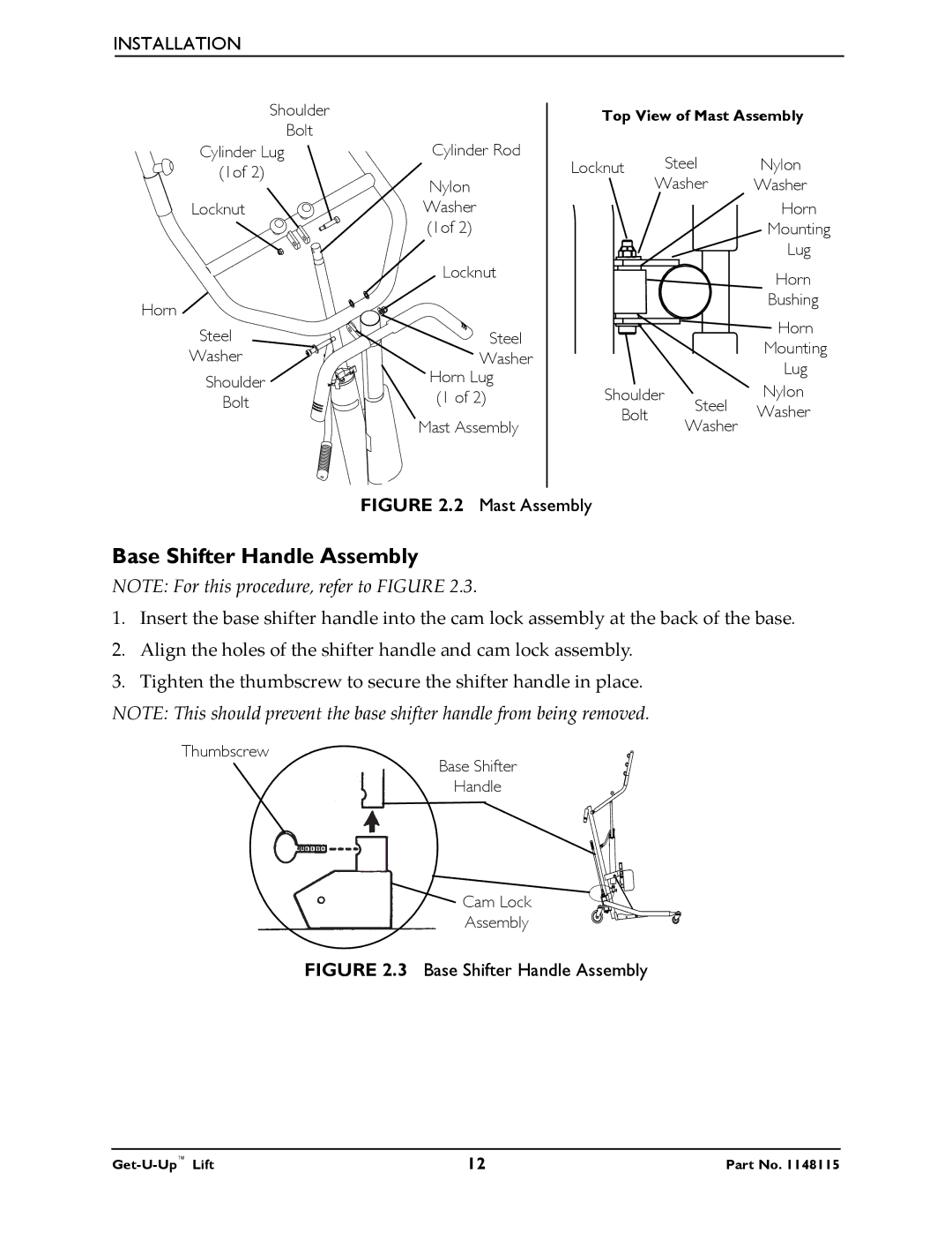
Base Shifter Handle Assembly
NOTE: For this procedure, refer to FIGURE 2.3.
1.Insert the base shifter handle into the cam lock assembly at the back of the base.
2.Align the holes of the shifter handle and cam lock assembly.
3.Tighten the thumbscrew to secure the shifter handle in place.
NOTE: This should prevent the base shifter handle from being removed.
Thumbscrew
Base Shifter
Handle
Cam Lock
Assembly