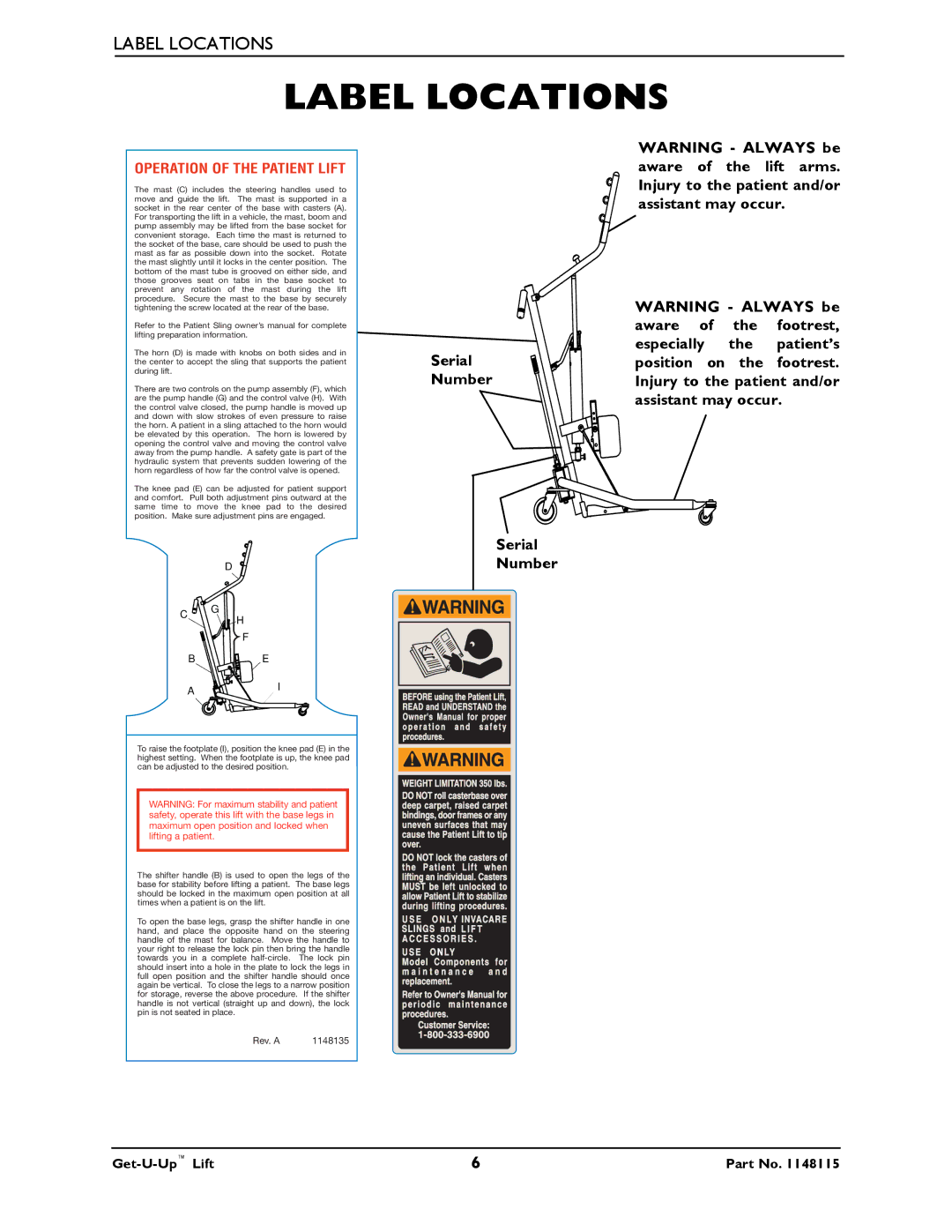
LABEL LOCATIONS
LABEL LOCATIONS
OPERATION OF THE PATIENT LIFT
The mast (C) includes the steering handles used to move and guide the lift. The mast is supported in a socket in the rear center of the base with casters (A). For transporting the lift in a vehicle, the mast, boom and pump assembly may be lifted from the base socket for convenient storage. Each time the mast is returned to the socket of the base, care should be used to push the mast as far as possible down into the socket. Rotate the mast slightly until it locks in the center position. The bottom of the mast tube is grooved on either side, and those grooves seat on tabs in the base socket to prevent any rotation of the mast during the lift procedure. Secure the mast to the base by securely tightening the screw located at the rear of the base.
Refer to the Patient Sling owner’s manual for complete lifting preparation information.
The horn (D) is made with knobs on both sides and in the center to accept the sling that supports the patient during lift.
There are two controls on the pump assembly (F), which are the pump handle (G) and the control valve (H). With the control valve closed, the pump handle is moved up and down with slow strokes of even pressure to raise the horn. A patient in a sling attached to the horn would be elevated by this operation. The horn is lowered by opening the control valve and moving the control valve away from the pump handle. A safety gate is part of the hydraulic system that prevents sudden lowering of the horn regardless of how far the control valve is opened.
The knee pad (E) can be adjusted for patient support and comfort. Pull both adjustment pins outward at the same time to move the knee pad to the desired position. Make sure adjustment pins are engaged.
| D | |
C | G | |
H | ||
|
F
B E
AI
To raise the footplate (I), position the knee pad (E) in the highest setting. When the footplate is up, the knee pad can be adjusted to the desired position.
WARNING: For maximum stability and patient safety, operate this lift with the base legs in maximum open position and locked when lifting a patient.
The shifter handle (B) is used to open the legs of the base for stability before lifting a patient. The base legs should be locked in the maximum open position at all times when a patient is on the lift.
To open the base legs, grasp the shifter handle in one hand, and place the opposite hand on the steering handle of the mast for balance. Move the handle to your right to release the lock pin then bring the handle towards you in a complete
Rev. A | 1148135 |
Serial
Number
Serial
Number
WARNING - ALWAYS be aware of the lift arms. Injury to the patient and/or assistant may occur.
WARNING - ALWAYS be aware of the footrest, especially the patient’s position on the footrest. Injury to the patient and/or assistant may occur.
