Manuals
/
Invacare
/
Personal Care
/
Mobility Aid
Invacare
L-4, L-3
user manual
Battery wiring label is on the underside Battery box door
Models:
L-3
L-4
1
18
56
56
Download
56 pages
51.87 Kb
15
16
17
18
19
20
21
22
Troubleshooting
Install
Error codes
Symbols
Warranty
Dimension
Maintenance
Resetting the Circuit Breaker
Accessories
Operation Information Setup
Page 18
Image 18
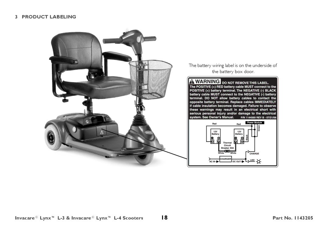
3 PRODUCT LABELING
The battery wiring label is on the underside of
the battery box door.
Invacare® Lynx™
L-3
&
Invacare® Lynx™
L-4
Scooters
18
Part No. 1143205
Page 17
Page 19
Page 18
Image 18
Page 17
Page 19
Contents
Invacare Lynx L-3 Invacare Lynx L-4
Contents
Wheels and Casters
Symbols
General
Limited Warranty
Safety
General Guidelines
Operation Information Setup
Transport
Do not operate on roads, streets or highways
Stairways and Escalators
Repair or Service Information
Safety/Handling of Powered Scooters
Safety
Safety
Storage
Rain Test
Battery
Weight Training
Electrical and Grounding
Disposal
Weight Limitation
Weight limitation is 300 lbs
EMI Information
Powered Wheelchair Electromagnetic Interference EMI
Safety
Product Labeling
Serial Number Label
Battery wiring label is on the underside Battery box door
Seat Dimensions
Technical Data
Typical Product Parameters Overall Dimensions
Arm Dimensions
Weight
Wheels
Driving
Safety Inspection Checklists
Inspection
Inspect/Adjust Initially
Inspect/Adjust Weekly
Inspect/Adjust Monthly
Inspect/Adjust Periodically
Operating the Powered Scooter
For this procedure, refer to .1 on
Control Panel
Operating the Scooter
Control Panel
Operating the Powered Scooter
Engaging/Disengaging the Brake Release Lever
Push Forward to Disengage
Pull Back to Engage Drive
Seat and Arms
Removing/Installing the Seat
Installing
Removing
Adjusting Seat Height
Adjusting Seat Height
Adjusting 90 Seat Swivel
Adjusting 90 Seat Swivel
Adjusting the Arm Width
Replacing Armrest Pads
Tiller locks into one of three positions.
Tiller Adjustment
Adjusting the Tiller Angle
Storage
Removing/Installing the Drive Wheels
Wheels and Casters
Removing/Installing the Front Wheel
Place keystock* in cutout on drive shaft as shown in Figure
Batteries
Recommended Battery Type
Recommended Battery Type
Removing/Installing the Battery Box
Removing/Installing the Batteries
For this procedure, refer to .3 on
Installing
Removing/Installing the Batteries
Charging the Batteries
The battery charger light will be Yellow or RED
Transporting
Transporting the Scooter
Disassembling
Release
Seat Post Assembly
Assembling
Lever
Accessories
Installing/Removing the Accessory Tube
Installing/Removing the Crutch/Cane Holder
Installing/Removing the Crutch/Cane Holder
Installing/Removing the Safety Flag
Installing/Removing the Safety Flag
Reverse this procedure to remove the walker holder
Installing/Removing/Using the Walker Holder
Installing/Removing the Walker Holder
Using the Walker Holder
Installing/Removing the Rear Mounted Basket
Installing/Removing the Rear Mounted Basket
Maintenance
Suggested Maintenance Procedures
Troubleshooting
General Troubleshooting
Slowly decelerating to a stop
Service Indicator Error Codes
For the following table, refer to .1 on
Resetting the Circuit Breaker
Seat Circuit Breaker Button
USA
Top
Page
Image
Contents