Arrow FWD, RWD, MWD specifications
Invacare is a renowned name in the field of mobility technologies, consistently innovating and enhancing the mobility devices market. Among its outstanding offerings are the Invacare MWD (Mid Wheel Drive), RWD (Rear Wheel Drive), and Arrow FWD (Front Wheel Drive) wheelchairs. Each of these models serves unique user needs, featuring distinct designs and functionalities.The Invacare MWD is engineered for exceptional maneuverability. Its mid-wheel drive technology provides a centralized drive wheel, allowing for tight turns and easy navigation in confined spaces. This makes the MWD particularly suitable for indoor use, where space can be limited. The MWD also features advanced suspension systems, offering superior shock absorption. This results in a smoother ride over various terrains, enhancing user comfort and stability.
On the other hand, the Invacare RWD focuses on robust outdoor performance. With its rear-wheel drive configuration, this model has excellent traction and provides powerful acceleration. The RWD is designed for versatility, equipped with larger wheels that can handle uneven terrain while providing a stable ride. Its durable construction ensures enhanced longevity, making it an ideal choice for users who lead an active lifestyle and require reliable mobility solutions on rugged ground.
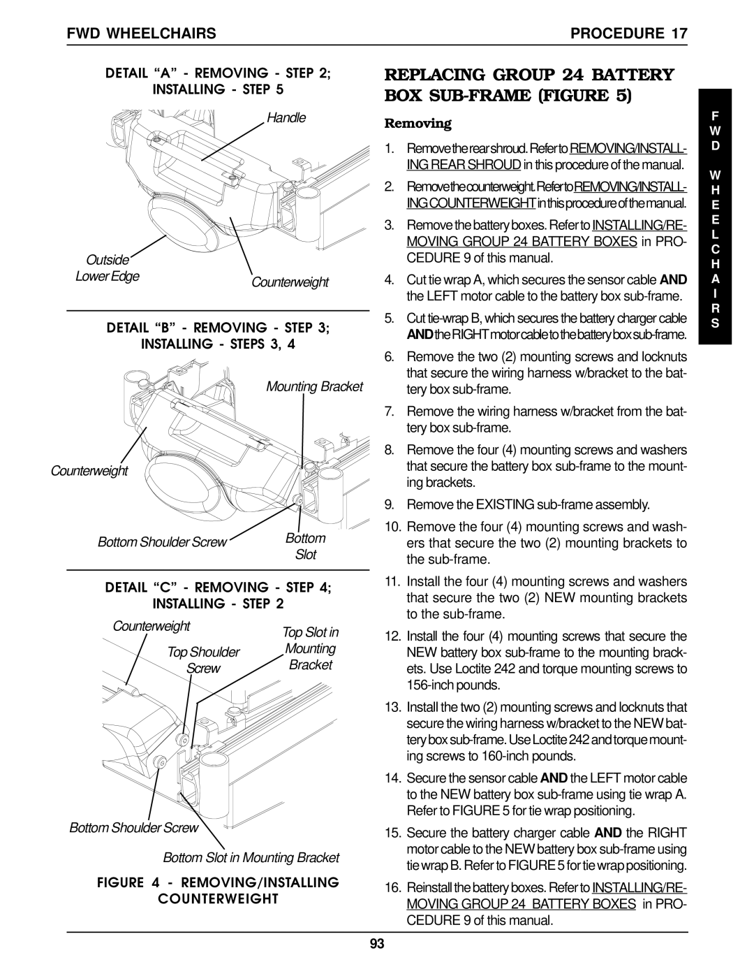
The Arrow FWD wheelchair brings another dimension with its front-wheel drive system. This design allows users to easily navigate obstacles as the front wheels can pivot over them. The Arrow FWD is particularly suited for both indoor and outdoor use, as it combines the agility of the MWD with the stability seen in the RWD. It features a compact design, making it easier for users to position themselves in various settings and social situations.
All three models utilize Invacare's cutting-edge technologies, such as advanced control systems and customizable seating options, enabling users to find their optimal comfort and support levels. The customizable features also cater to individual user needs, promoting enhanced independence.
In summary, Invacare’s MWD, RWD, and Arrow FWD wheelchairs represent an impressive blend of functionality, durability, and user-centric design. Each model presents its own unique technologies and attributes, allowing users to make informed choices based on their specific mobility requirements, lifestyle, and preferences. Whether navigating tight indoor spaces or tackling outdoor challenges, Invacare’s range of wheelchairs ensures that users can experience mobility with confidence and ease.

