MWD WHEELCHAIRS

PROCEDURE 15


This Procedure includes the following:

Removing/Installing Group 24 Battery Box Sub-Frame Removing/Installing Group 22 Battery Box Tray Converting Group 22 Batteries To Group 24 Batteries Shock Replacement

Shock Spring Replacement

Replacing Stabilizer Fork Assembly

Replacing Stabilizer Wheels

Replacing Stabilizer Cylinder Springs

Adjusting Weight Distribution

Adjusting Stabilizers

Installing/Removing Gearbox

Replacing Suspension Arm

WARNING

After ANY adjustments, repair or service and BE- FORE use, make sure that all attaching hardware is tightened securely - otherwise injury or dam- age may result.

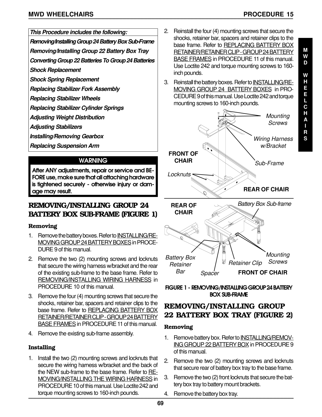
2.Reinstall the four (4) mounting screws that secure the shocks, retainer bar, spacers and retainer clips to the base frame. Refer to REPLACING BATTERY BOX RETAINER/RETAINERCLIP-GROUP24BATTERY BASE FRAMES in PROCEDURE 11 of this manual. Use Loctite 242 and torque mounting screws to 160- inch pounds.

3.Reinstall the battery boxes. Refer to INSTALLING/RE- MOVING GROUP 24 BATTERY BOXES in PRO- CEDURE 9of this manual. Use Loctite 242 andtorque mounting screws to 160-inch pounds.

Mounting

Screws

Wiring Harness

w/Bracket

FRONT OF

CHAIRSub-Frame

Locknuts

REAR OF CHAIR

M W D

W H E E L C H A I R S

REMOVING/INSTALLING GROUP 24

REAR OF


Battery Box Sub-frame

BATTERY BOX SUB-FRAME (FIGURE 1)

CHAIR


Removing


1. Removethebatteryboxes.Referto INSTALLING/RE-


MOVING GROUP 24 BATTERY BOXES in PROCE-


DURE 9 of this manual.


Mounting

2. Remove the two (2) mounting screws and locknuts

Battery Box


Retainer Clip

Screws

that secure the wiring harness w/bracket and the rear

Retainer


of the existing sub-frame to the base frame. Refer to

Bar

Spacer

FRONT OF CHAIR

REMOVING/INSTALLING WIRING HARNESS in


PROCEDURE 10 of this manual.

FIGURE 1 - REMOVING/INSTALLINGGROUP24BATTERY

3. Remove the four (4) mounting screws that secure the

BOX SUB-FRAME

shocks, retainer bar, spacers and retainer clips to the

REMOVING/INSTALLING GROUP

base frame. Refer to REPLACING BATTERY BOX

22 BATTERY BOX TRAY (FIGURE 2)

RETAINER/RETAINERCLIP-GROUP24BATTERY

BASE FRAMES in PROCEDURE 11 of this manual.

Removing

4. Remove the existing sub-frame assembly.

1. Remove battery box. Refer to INSTALLING/REMOV-


Installing

ING GROUP 22 BATTERY BOX in PROCEDURE 9

of this manual.


1. Install the two (2) mounting screws and locknuts that

2. Remove the two (2) mounting screws and locknuts

secure the wiring harness w/bracket and the back of

that secure rear of battery box tray to the base frame.

the NEW sub-frame to the base frame. Refer to RE-

3. Remove the two (2) front locknuts that secure the bat-

MOVING/INSTALLING THE WIRING HARNESS in

PROCEDURE 10 of this manual. Use Loctite 242 and

tery box tray to battery mount brackets.

torque mounting screws to 160-inch pounds.

4. Remove the battery box tray.


69

Page 69
Image 69
Invacare REMOVING/INSTALLING Group, Battery BOX Tray Figure, Battery BOX SUB-FRAME Figure, MWD Wheelchairs Procedure

Arrow FWD, RWD, MWD specifications

Invacare is a renowned name in the field of mobility technologies, consistently innovating and enhancing the mobility devices market. Among its outstanding offerings are the Invacare MWD (Mid Wheel Drive), RWD (Rear Wheel Drive), and Arrow FWD (Front Wheel Drive) wheelchairs. Each of these models serves unique user needs, featuring distinct designs and functionalities.

The Invacare MWD is engineered for exceptional maneuverability. Its mid-wheel drive technology provides a centralized drive wheel, allowing for tight turns and easy navigation in confined spaces. This makes the MWD particularly suitable for indoor use, where space can be limited. The MWD also features advanced suspension systems, offering superior shock absorption. This results in a smoother ride over various terrains, enhancing user comfort and stability.

On the other hand, the Invacare RWD focuses on robust outdoor performance. With its rear-wheel drive configuration, this model has excellent traction and provides powerful acceleration. The RWD is designed for versatility, equipped with larger wheels that can handle uneven terrain while providing a stable ride. Its durable construction ensures enhanced longevity, making it an ideal choice for users who lead an active lifestyle and require reliable mobility solutions on rugged ground.

The Arrow FWD wheelchair brings another dimension with its front-wheel drive system. This design allows users to easily navigate obstacles as the front wheels can pivot over them. The Arrow FWD is particularly suited for both indoor and outdoor use, as it combines the agility of the MWD with the stability seen in the RWD. It features a compact design, making it easier for users to position themselves in various settings and social situations.

All three models utilize Invacare's cutting-edge technologies, such as advanced control systems and customizable seating options, enabling users to find their optimal comfort and support levels. The customizable features also cater to individual user needs, promoting enhanced independence.

In summary, Invacare’s MWD, RWD, and Arrow FWD wheelchairs represent an impressive blend of functionality, durability, and user-centric design. Each model presents its own unique technologies and attributes, allowing users to make informed choices based on their specific mobility requirements, lifestyle, and preferences. Whether navigating tight indoor spaces or tackling outdoor challenges, Invacare’s range of wheelchairs ensures that users can experience mobility with confidence and ease.