Tumblers – T30 and T45
WARNING
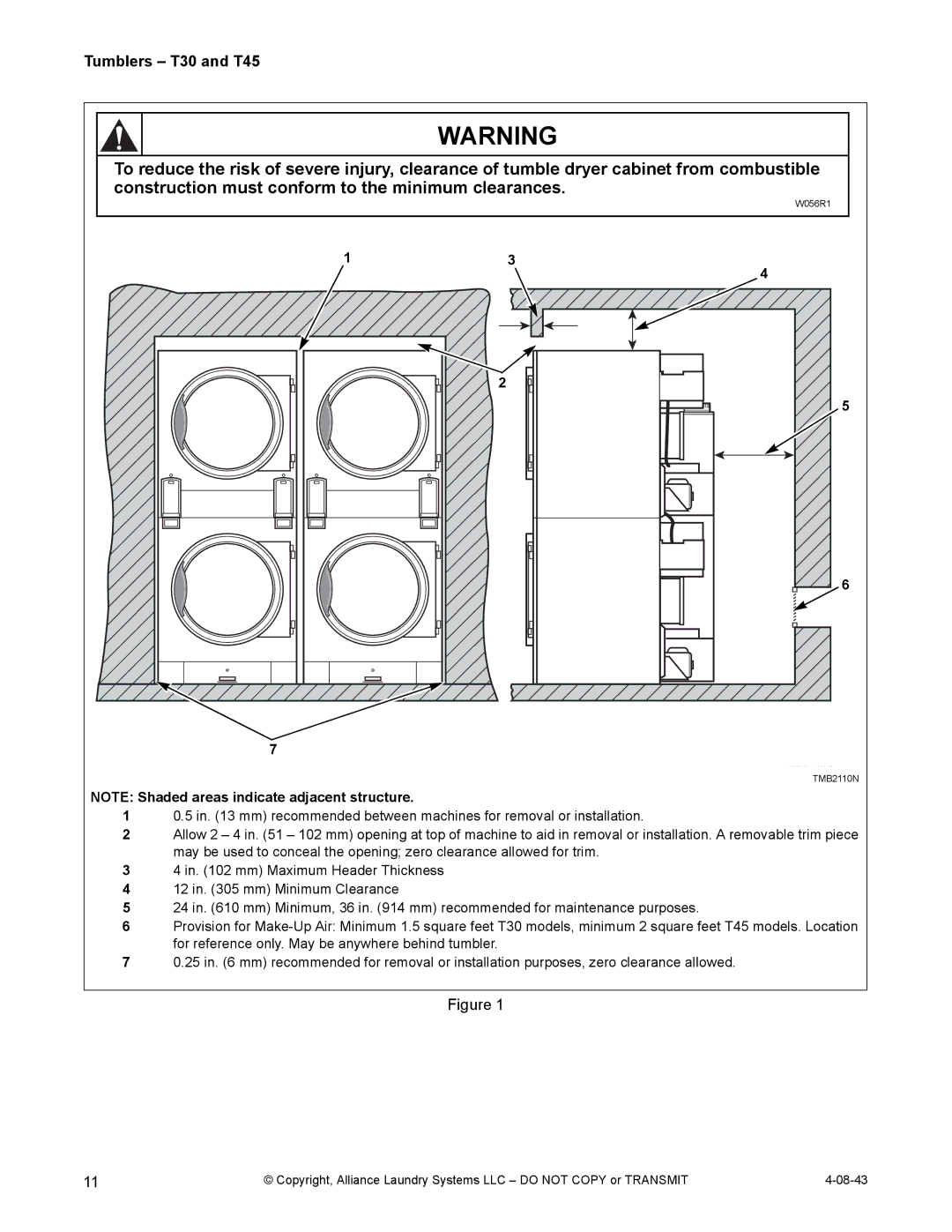
To reduce the risk of severe injury, clearance of tumble dryer cabinet from combustible construction must conform to the minimum clearances.
W056R1
7 |
1 | 3 |
| 2 |
4
5
6
TMB2110N
NOTE: Shaded areas indicate adjacent structure.
10.5 in. (13 mm) recommended between machines for removal or installation.
2Allow 2 – 4 in. (51 – 102 mm) opening at top of machine to aid in removal or installation. A removable trim piece may be used to conceal the opening; zero clearance allowed for trim.
34 in. (102 mm) Maximum Header Thickness
412 in. (305 mm) Minimum Clearance
524 in. (610 mm) Minimum, 36 in. (914 mm) recommended for maintenance purposes.
6Provision for
70.25 in. (6 mm) recommended for removal or installation purposes, zero clearance allowed.
Figure 1
11 | © Copyright, Alliance Laundry Systems LLC – DO NOT COPY or TRANSMIT |