Tumblers – T30 and T45
3 ![]()
![]()
![]()
2
1
4
5TMB2103N
TMB2103N
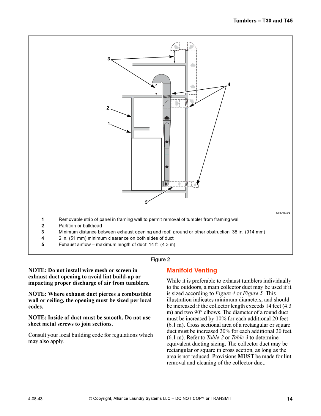
1Removable strip of panel in framing wall to permit removal of tumbler from framing wall
2Partition or bulkhead
3Minimum distance between exhaust opening and roof, ground or other obstruction: 36 in. (914 mm)
42 in. (51 mm) minimum clearance on both sides of duct
5Exhaust airflow – maximum length of duct: 14 ft. (4.3 m)
Figure 2
NOTE: Do not install wire mesh or screen in exhaust duct opening to avoid lint
NOTE: Where exhaust duct pierces a combustible wall or ceiling, the opening must be sized per local codes.
NOTE: Inside of duct must be smooth. Do not use sheet metal screws to join sections.
Consult your local building code for regulations which may also apply.
Manifold Venting
While it is preferable to exhaust tumblers individually to the outdoors, a main collector duct may be used if it is sized according to Figure 4 or Figure 5. This illustration indicates minimum diameters, and should be increased if the collector length exceeds 14 feet (4.3
m)and two 90° elbows. The diameter of a round duct must be increased by 10% for each additional 20 feet (6.1 m). Cross sectional area of a rectangular or square duct must be increased 20% for each additional 20 feet (6.1 m). Refer to Table 2 or Table 3 to determine equivalent ducting sizing. The collector duct may be rectangular or square in cross section, as long as the area is not reduced. Provisions MUST be made for lint removal and cleaning of the collector duct.
© Copyright, Alliance Laundry Systems LLC – DO NOT COPY or TRANSMIT | 14 |