
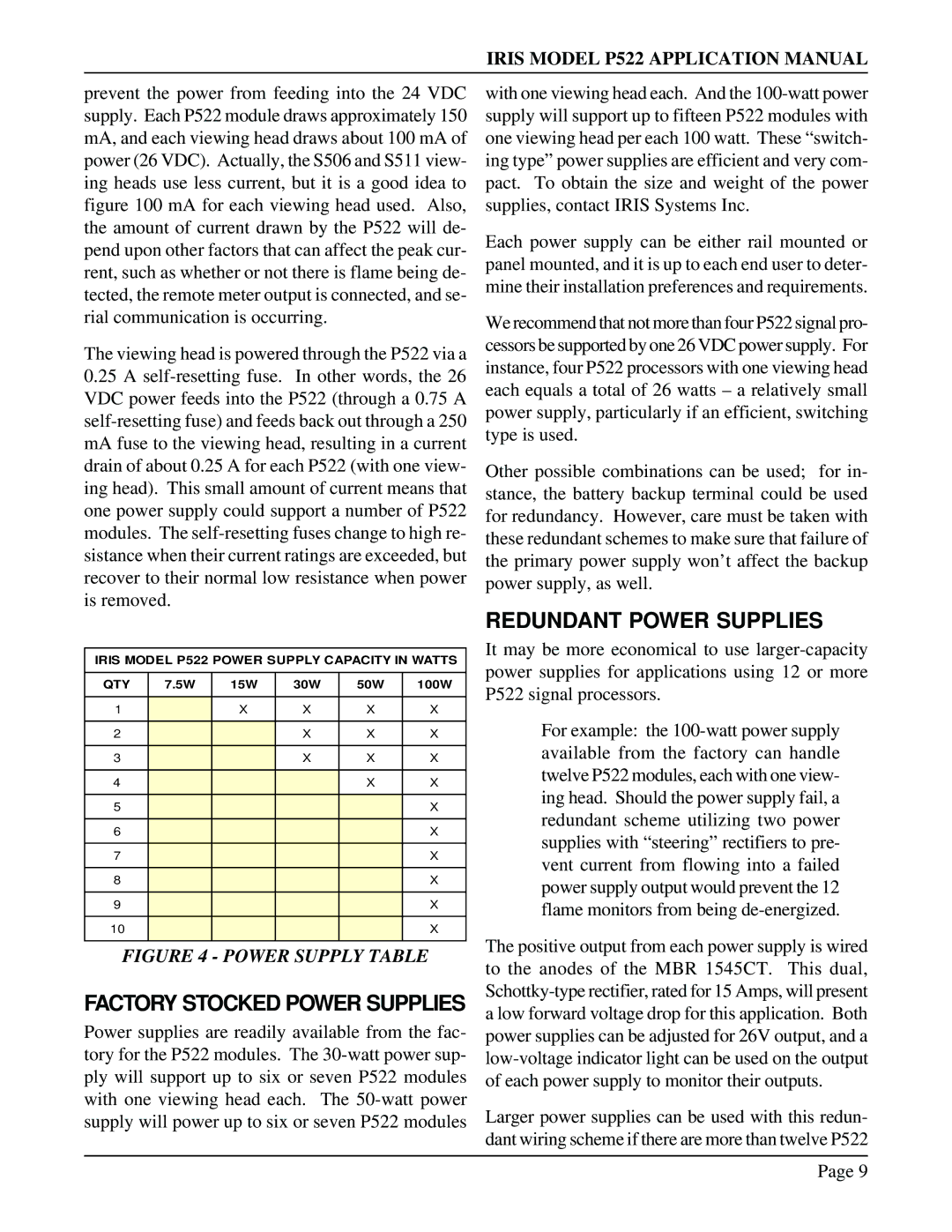
P522 specifications
The IRIS P522 is a highly advanced smart device characterized by its cutting-edge features, technologies, and remarkable performance capabilities. Designed for seamless integration into both personal and professional environments, the P522 stands out as a versatile tool for various applications, ranging from productivity enhancement to entertainment.One of the main features of the IRIS P522 is its state-of-the-art display technology. The device sports a high-resolution touchscreen that provides vibrant colors and sharp images, ensuring a remarkable visual experience. This impressive display is paired with an ultra-responsive multi-touch interface, allowing users to interact effortlessly with the device, facilitating increased efficiency in tasks such as data entry, navigation, and media consumption.
The performance of the IRIS P522 is powered by a robust processor and ample RAM, enabling it to handle multitasking with ease. This ensures that users can run multiple applications simultaneously without experiencing lags or slowdowns. Additionally, the device incorporates advanced cooling technologies, which help maintain optimal operating temperatures even during intensive use, ensuring reliability over extended periods.
Connectivity is another significant aspect of the IRIS P522. Equipped with the latest wireless technologies, including Wi-Fi 6 and Bluetooth 5.0, the device allows for lightning-fast data transfer rates and seamless connections to a variety of accessories. This makes it an ideal choice for professionals who require constant communication and quick access to cloud-based resources.
Security features are paramount in today's digital landscape, and the IRIS P522 does not disappoint. It includes biometric authentication options such as fingerprint recognition and facial recognition, providing users with a secure way to access their device and data. This focus on security is further reinforced by regular software updates that ensure protection against the latest threats.
Battery life is another highlight of the IRIS P522, with an energy-efficient design that offers extended usage without frequent recharges. This is particularly beneficial for users on the go, as it enables prolonged productivity without being tethered to a power supply.
In conclusion, the IRIS P522 is a remarkable device that harmoniously blends advanced features, powerful technology, and user-centric design. With its stunning display, high performance, effortless connectivity, robust security measures, and extended battery life, the P522 caters to the needs of users in various contexts, making it an indispensable addition to modern digital life.