CV-A33CL
5.3.3. Camera Link interface
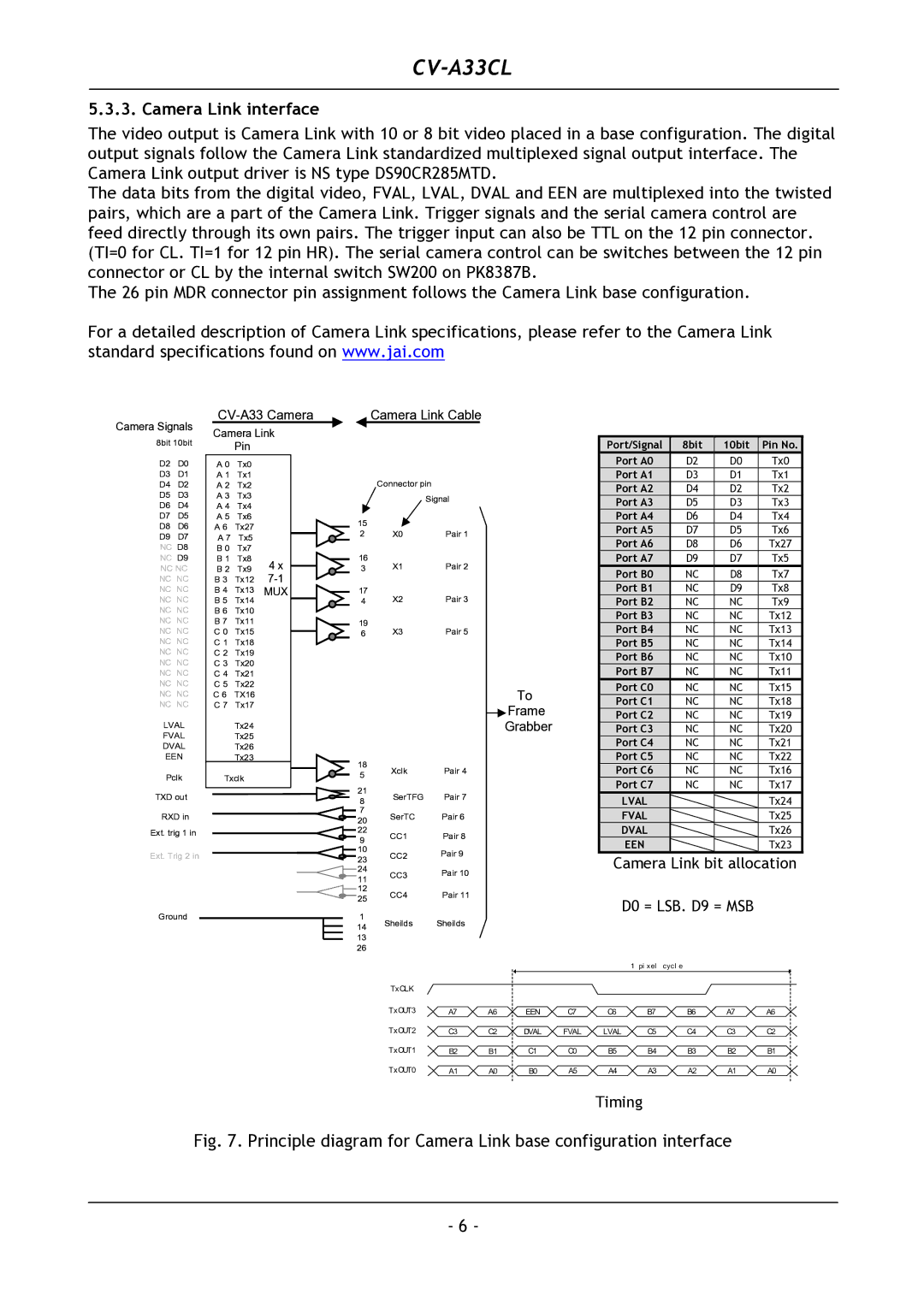
The video output is Camera Link with 10 or 8 bit video placed in a base configuration. The digital output signals follow the Camera Link standardized multiplexed signal output interface. The Camera Link output driver is NS type DS90CR285MTD.
The data bits from the digital video, FVAL, LVAL, DVAL and EEN are multiplexed into the twisted pairs, which are a part of the Camera Link. Trigger signals and the serial camera control are feed directly through its own pairs. The trigger input can also be TTL on the 12 pin connector. (TI=0 for CL. TI=1 for 12 pin HR). The serial camera control can be switches between the 12 pin connector or CL by the internal switch SW200 on PK8387B.
The 26 pin MDR connector pin assignment follows the Camera Link base configuration.
For a detailed description of Camera Link specifications, please refer to the Camera Link standard specifications found on www.jai.com
CV-A33 Camera
Camera Link Cable
Camera Signals | Camera Link | ||||
8bit 10bit | |||||
| Pin |
| |||
D2 | D0 | A 0 | Tx0 |
| |
D3 | D1 | A 1 | Tx1 |
| |
D4 | D2 | A 2 | Tx2 |
| |
D5 | D3 | A 3 | Tx3 |
| |
D6 | D4 | A 4 | Tx4 |
| |
D7 | D5 | A 5 | Tx6 |
| |
D8 | D6 | A 6 | Tx27 |
| |
D9 | D7 | A 7 | Tx5 |
| |
NC D8 | B 0 | Tx7 |
| ||
NC D9 | B 1 | Tx8 | 4 x | ||
NC NC | B 2 | Tx9 | |||
NC NC | B 3 | Tx12 | |||
NC NC | B 4 | Tx13 | MUX | ||
NC NC | B 5 | Tx14 |
| ||
NC NC | B 6 | Tx10 |
| ||
NC NC | B 7 | Tx11 |
| ||
NC NC | C 0 | Tx15 |
| ||
NC NC | C 1 | Tx18 |
| ||
NC NC | C 2 | Tx19 |
| ||
NC NC | C 3 | Tx20 |
| ||
NC NC | C 4 | Tx21 |
| ||
NC NC | C 5 | Tx22 |
| ||
NC NC | C 6 | TX16 |
| ||
NC NC | C 7 | Tx17 |
| ||
LVAL |
| Tx24 |
| ||
FVAL |
| Tx25 |
| ||
DVAL |
| Tx26 |
| ||
EEN |
| Tx23 |
| ||
Pclk | Txclk |
| |||
TXD out |
|
|
| ||
RXD in
Ext. trig 1 in
Ext. Trig 2 in
Ground
Connector pin
|
| Signal |
15 |
|
|
2 | X0 | Pair 1 |
16 | X1 | Pair 2 |
3 | ||
17 | X2 | Pair 3 |
4 | ||
19 | X3 | Pair 5 |
6 |
To
Frame
Grabber
18 | Xclk | Pair 4 | |
5 | |||
|
| ||
21 | SerTFG | Pair 7 | |
8 | |||
7 | SerTC | Pair 6 | |
20 | |||
22 | CC1 | Pair 8 | |
9 | |||
10 | CC2 | Pair 9 | |
23 | |||
24 | CC3 | Pair 10 | |
11 | |||
12 | CC4 | Pair 11 | |
25 | |||
|
| ||
1 | Sheilds | Sheilds | |
14 | |||
|
|
13
26
Port/Signal | 8bit | 10bit | Pin No. |
|
| D2 | D0 | Tx0 |
| Port A1 | D3 | D1 | Tx1 |
| Port A2 | D4 | D2 | Tx2 |
| Port A3 | D5 | D3 | Tx3 |
| Port A4 | D6 | D4 | Tx4 |
| Port A5 | D7 | D5 | Tx6 |
| Port A6 | D8 | D6 | Tx27 |
| Port A7 | D9 | D7 | Tx5 |
|
| NC | D8 | Tx7 |
| Port B1 | NC | D9 | Tx8 |
| Port B2 | NC | NC | Tx9 |
| Port B3 | NC | NC | Tx12 |
| Port B4 | NC | NC | Tx13 |
| Port B5 | NC | NC | Tx14 |
| Port B6 | NC | NC | Tx10 |
| Port B7 | NC | NC | Tx11 |
|
| NC | NC | Tx15 |
|
| NC | NC | Tx18 |
| Port C2 | NC | NC | Tx19 |
| Port C3 | NC | NC | Tx20 |
| Port C4 | NC | NC | Tx21 |
| Port C5 | NC | NC | Tx22 |
| Port C6 | NC | NC | Tx16 |
| Port C7 | NC | NC | Tx17 |
|
|
|
| Tx24 |
| FVAL |
|
| Tx25 |
DVAL ![]()
![]() Tx26
Tx26
Tx23
Camera Link bit allocation
D0 = LSB. D9 = MSB
|
|
|
|
| 1 | pi xel | cycl e |
|
|
TxCLK |
|
|
|
|
|
|
|
|
|
TxOUT3 | A7 | A6 | EEN | C7 | C6 | B7 | B6 | A7 | A6 |
TxOUT2 | C3 | C2 | DVAL | FVAL | LVAL | C5 | C4 | C3 | C2 |
TxOUT1 | B2 | B1 | C1 | C0 | B5 | B4 | B3 | B2 | B1 |
TxOUT0 | A1 | A0 | B0 | A5 | A4 | A3 | A2 | A1 | A0 |
Timing
Fig. 7. Principle diagram for Camera Link base configuration interface
- 6 -