GX-A604/GX-A602/GX-A3001
Location and mounting
Installation Warnings and Tips
Introduction Included items
Mounting the Amplifier
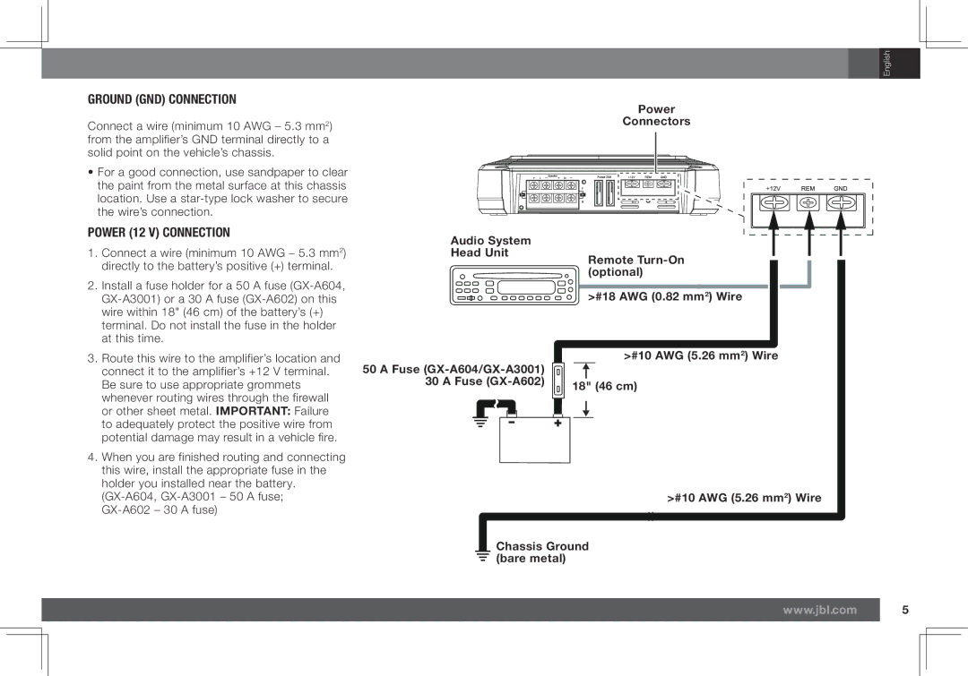
Installation Location
Using the Connectors
Power and ground connections
Loosen Screw Insert Wire
Under Washer
Power Connectors
Power 12 V Connection
#18 AWG 0.82 mm2 Wire #10 AWG 5.26 mm2 Wire 18 46 cm
Audio System Head Unit
GX-A604 speaker connections 4-Channel operation
Speaker and input connections
Minimum speaker impedance 2 ohms each
Front Left Speaker Front Right Speaker
Front Line Outputs Rear Line Outputs
GX-A604 Input Connections 4-CHANNEL Operation
Subwoofer
GX-A604 Speaker Connections 3-CHANNEL Operation
Adapter
GX-A604 Input Connections 3-CHANNEL Operation
Source Unit
Front Line Outputs Subwoofer Line Output
Left Speaker Right Speaker
GX-A604 speaker connections 2-channel operation
Minimum speaker impedance 4 ohms each
Front Line Outputs
GX-A604 Input Connections 2-CHANNEL Operation
GX-A602 speaker Connections 2-channel operation
Using the speaker-level inputs
Line Outputs Source Unit
GX-A602 Input Connections 2-CHANNEL Operation
Minimum speaker impedance 4 ohms
GX-A602 speaker connections bridged operation
Output
GX-A602 Input Connections Bridged Operation
Ohm Subwoofer
Gx-a3001 speaker connections
GX-A3001 Input Connection
GX-A604
Controls, input connections and Indicators
Level Control Power Indicator
Indicator
GX-A604 3-Channel Operation
Set the crossover controls
GX-A604 4-Channel Operation
Smaller Speakers
GX-A604 2-CHANNEL Operation
Set the Input level
Crossover Filter switch
GX-A602 2-Channel Operation
GX-A602 Bridged Operation
Power LED
Power and Protection Leds
SET the Bass Boost
Protection LED
Problem Causes and Solutions
Troubleshooting
Problem Causes and Solutions
GX-A604 GX-A602 GX-A3001
Specifications
Verstärker
Einleitung Mitgelieferte Bauteile
Warnungen und Tipps zur Installation
Aufstellung und Montage
Verstärker der GX-Serie x
Montage DES Verstärkers
Installationsort
Schraube Kabel unter Lösen Scheibe legen
Stromversorgungs- und Erdungsanschlüsse
Handhabung der Anschlüsse
Versorgungsanschluss 12
MASSE-ANSCHLUSS GND
GX-A604 Lautsprecheranschlüsse 4-Kanal-Funktion
Lautsprecher und Eingangsanschlüsse
Minimale Lautsprecherimpedanz 2 Ohm jeder
Lautsprecher vorne links Lautsprecher vorne rechts
Front-Line-Ausgänge Rückwärtige Line-Ausgänge
GX-A604 Eingangsanschlüsse 4-KANAL-FUNKTION
GX-A604 Lautsprecheranschlüsse 3-KANAL-FUNKTION
Front-Line-Ausgänge Subwoofer-Line-Ausgang
GX-A604 Eingangsanschlüsse 3-KANAL-FUNKTION
Quellgerät
Lautsprecher links Lautsprecher rechts
GX-A604 Lautsprecheranschlüsse 2-Kanal-Funktion
Minimale Lautsprecherimpedanz 4 Ohm jeder
Front-Line-Ausgänge
GX-A604 Eingangsanschlüsse 2-KANAL-FUNKTION
GX-A602 Lautsprecheranschlüsse 2-Kanal-Funktion
Verwendung der Lautsprecher-Pegeleingänge
Line-Ausgänge Quellgerät
GX-A602 Eingangsanschlüsse 2-KANAL-FUNKTION
Minimale Lautsprecherimpedanz 4 Ohm
GX-A602 Lautsprecheranschlüsse Brückenbetrieb
„Y-AdapterSubwoofer Ausgang Quellgerät
GX-A602 Eingangsanschlüsse Brückenbetrieb
Ohm-Subwoofer
GX-A3001 Lautsprecheranschlüsse
„Y-Adapter Subwoofer-Ausgang Quellgerät
GX-A3001 Eingangsanschluss
Bedienfeld, Eingangsanschlüsse und Anzeigen
Lautsprecherpegel Frequenweichen Bassverstärkungsschalter
GX-A604 4-Kanal-Funktion
Frequenzweichenregler einstellen
GX-A604 3-Kanal-Funktion
Rückwärtiger Frequenzweichenregler Wenn der rückwärtige
Rückwärtiger Frequenzweichen-Filterschalter Stellen Sie den
GX-A604 2-KANAL-FUNKTION
Und kleinere
GX-A602 2-Kanal-Funktion
Eingangspegel einstellen
GX-A602 Brückenbetrieb
Frequenzweichen-Filterschalter
BETRIEBS- UND SCHUTZ-LEDS
Bassverstärkung Einstellen
BETRIEBS-LED
SCHUTZ-LED
Fehlerbehebung
Problem Ursachen UND Abhilfen
Deutsch
Technische Daten
Amplificateur de puissance
Avertissements et conseils sur linstallation
Emplacement et montage
Introduction Éléments inclus
Amplificateur série GX x
Montage DE Lamplificateur
Emplacement DE Linstallation
Utilisation des connecteurs
Connexions dalimentation et de masse
Desserrer la vis Insérer le fil
Sous la rondelle
Connecteurs Dalimentation
Connexion Dalimentation 12
Fusible 50 a GX-A604/GX-A3001 Fusible 30 a GX-A602
Fil #18AWG 0,82 mm2 Fil #10AWG 5,26 mm2 46 cm
Impédance minimale des haut-parleurs 2 ohms chacun
Connexions aux haut-parleurs et des entrées
Haut-parleur avant gauche Haut-parleur avant droit
Haut-parleur arrière gauche Haut-parleur arrière droit
Sorties ligne avant Sorties ligne arrière
Caisson de graves
Sorties ligne avant Ligne sortie du caisson de graves
Appareil source
Haut-parleur gauche Haut-parleur droit
Impédance minimale des haut-parleurs 4 ohms chacun
Sorties ligne avant
Utilisation dentrées de niveau haut-parleur
Sorties ligne Appareil source
Impédance minimale des haut-parleurs 4 ohms
Adaptateur en Y Sortie du
Connexions DES Entrées AU GX-A602 Fonctionnement Avec Pont
Caisson de graves 4 ohms
Connexions des haut-parleurs au GX-A3001
De graves
Connexions DES Entrées AU GX-A3001
Adaptateur en Y
Commandes, connexions dentrée et témoins
Commutateur de
GX-A604 fonctionnement avec 3 canaux
Réglage des commandes de répartition
GX-A604 fonctionnement avec 4 canaux
Haut-parleurs 6 et Et haut-parleurs plus petits
GX-A604 Fonctionnement Avec 2 Canaux
GX-A602 fonctionnement avec 2 canaux
Réglage du niveau dentrée
GX-A602 fonctionnement avec pont
Commutateur de filtre répartiteur
DEL Dalimentation ET DE Protection
Réglage DE Lamplification DES Graves
DEL D’ALIMENTATION
DEL DE Protection
Problème Causes ET Solutions
Résolution DES Problèmes
Problème Causes ET Solutions
Spécifications
Amplificatore di potenza
Collocazione e montaggio
Avvertenze e suggerimenti per linstallazione
Introduzione Parti incluse
Montaggio Dellamplificatore
Posizione DI Installazione
Uso dei connettori
Connessioni di alimentazione e terra
Allentare Inserire il filo
La vite Sotto la rondella Vite
Connettori di alimentazione
Connessione Dellalimentazione
Fusibile da 30A GX-A602
Filo n.18AWG 0,82 mm2 Filo n.10AWG 5,26 mm2 18 46 cm
Connessioni dei diffusori GX-A604 funzionamento a 4 canali
Connessioni dei diffusori e di ingresso
Impedenza minima dei diffusori 2 ohm ciascuno
Diffusore frontale sinistro Diffusore frontale destro
Uscite di linea anteriori Uscite di linea posteriori
Connessioni DI Ingresso GX-A604 Funzionamento a 4 Canali
Connessioni DEI Diffusori GX-A604 Funzionamento a 3 Canali
Adattatore a Y
Connessioni DI Ingresso GX-A604 Funzionamento a 3 Canali
Unità sorgente
Uscite di linea anteriori Uscita di linea del subwoofer
Diffusore sinistro Diffusore destro
Connessioni dei diffusori GX-A604 funzionamento a 2 canali
Impedenza minima dei diffusori 4 ohm ciascuno
Uscite di linea anteriori
Connessioni DI Ingresso GX-A604 Funzionamento a 2 Canali
Connessioni dei diffusori GX-A602 funzionamento a 2 canali
Uso degli ingressi del livello dei diffusori
Uscite di linea Unità sorgente
Connessioni DI Ingresso GX-A602 Funzionamento a 2 Canali
Impedenza minima dei diffusori 4 ohm
Connessioni dei diffusori GX-A602 funzionamento ponticellato
Adattatore a Y Uscita del
Connessioni DI Ingresso GX-A602 Funzionamento Ponticellato
Subwoofer da 4-Ohm
Connessioni dei diffusori gx-a3001
Connessione DI Ingresso GX-A3001
Del livello
Controlli, connessioni di ingresso e indicatori
Controllo
Protezione
Del livello
Spia di alimentazione
GX-A604 funzionamento a 3 canali
Impostazione dei controlli del crossover
GX-A604 funzionamento a 4 canali
Più piccoli
GX-A604 Funzionamento a 2 Canali
Diffusori da 4 e diffusori
GX-A602 funzionamento a 2 canali
Impostazione del livello di ingresso
GX-A602 funzionamento ponticellato
Interruttore del filtro di crossover
LED DI Alimentazione E Protezione
Impostazione DEL Boost DEI Bassi
LED DI Alimentazione
LED DI Protezione
Ricerca Guasti
Problema Cause E Soluzioni
Problema Cause E Soluzioni
Specifiche
Amplificador de potencia
Ubicación y montaje
Introducción Elementos incluidos
Advertencias y consejos de instalación
Amplificador Serie GX
Montaje DEL Amplificador
Lugar DE Instalación
Uso de los conectores
Conexiones de alimentación y a tierra
Aflojar tornillo Insertar cable
Bajo la arandela
Conexión DE Alimentación 12
Conexión a Tierra GND
Conexiones del altavoz GX-A604 Funcionamiento en 4 canales
Conexiones del altavoz y de entrada
Impedancia mínima del altavoz 2 ohmios cada uno
Altavoz frontal izquierdo Altavoz frontal derecho
Salidas de línea frontal Salida de línea posteriores
Conexiones DE Entrada GX-A604 Funcionamiento EN 4 Canales
Conexiones DEL Altavoz GX-A604 Funcionamiento EN 3 Canales
Adaptador tipo Y
Conexiones DE Entrada GX-A604 Funcionamiento EN 3 Canales
Unidad fuente
Salidas de línea frontal Salida de línea del subwoofer
Altavoz izquierdo Altavoz derecho
Conexiones del altavoz GX-A604 Funcionamiento en 2 canales
Impedancia mínima del altavoz 4 ohmios cada uno
Salidas de línea frontal
Conexiones DE Entrada GX-A604 Funcionamiento EN 2 Canales
Conexiones del altavoz GX-A602 funcionamiento de 2 canales
Uso de las entradas de nivel del altavoz
Salidas de línea Unidad fuente
Impedancia mínima del altavoz 4 ohmios
Conexiones del altavoz GX-A602 Funcionamiento puenteado
Adaptador tipo Y Salida del
Conexiones DE Entrada GX-A604 Funcionamiento Puenteado
Subwoofer de 4 ohmios
Conexiones del altavoz gx-a3001
Adaptador tipo Y Salida del subwoofer Unidad fuente
Conexiones DE Entrada GX-A3001
Controles, conexiones de entrada e indicadores
filtro de cruceta
Conmutador de
Protección
Control de nivel Indicador de Alimentación
GX-A604 Funcionamiento en 3 canales
Fijar los controles de cruceta
GX-A604 Funcionamiento en 4 canales
GX-A604 Funcionamiento EN 2 Canales
GX-A602 Funcionamiento en 2 canales
Fijar el nivel de entrada
GX-A602 Funcionamiento puenteado
Conmutador de filtro de cruceta
Potencia Y LED DE Protección
Fijar EL Bass Boost
LED DE Alimentación
LED DE Protección
Problema Causas Y Soluciones
Problemas Y Soluciones
Problema Causas Y Soluciones
Especificaciones
Усилитель
Предупреждения и советы
Введение Комплект поставки
Размещение и монтаж
Монтаж усилителя
Место установки
Ослабьте Вставьте провод Закрутите Винт Под шайбу
Силовое соединение и заземление
Использование клеммной колодки
Силовое соединение 12 в
ЗазеМление GND
Подключение динамиков к GX-A604 4-канальная система
Подключение динамиков и источника аудиосигнала
Минимальный импеданс каждого динамика 2 Ом
Передний левый динамик Передний правый динамик
Выходы передних каналов Выходы задних каналов
Источник аудиосигнала
Сабвуфер
ПодклюЧение динаМиков к GX-A604 3-канальная систеМа
Выходы передних каналов Выход канала сабвуфера
Образный адаптер
Левый динамик Правый динамик
Подключение динамиков к GX-A604 2-канальная система
Минимальный импеданс каждого динамика 4 Ом
Выходы передних каналов
Подключение динамиков к GX-A602 2-канальная система
Использование высокоуровневых входов
Линейные выходы Источник аудиосигнала
Минимальный импеданс сабвуфера 4 Ом
Подключение динамиков к GX-A602 мостовая схема
Образный адаптер Выход Сабвуфера Источник аудиосигнала
ПодклюЧение истоЧника аудиосиГнала к GX-A602 Мостовая схеМа
Сабвуфер 4 Ом
Подключение динамиков к GX-A3001
Образный Выход сабвуфера Адаптер Источник Аудиосигнала
ПодклюЧение истоЧника аудиосиГнала к GX-A3001
Органы управления, входные разъемы и индикаторы
GX-A602
GX-A604 3-канальная система
Управление кроссовером
GX-A604 4-канальная система
GX-A604 2-канальная систеМа
5-дюймовые Дюймовые динамики Динамики Меньше
GX-A602 мостовая схема
Управление усилением сигналов
GX-A602 2-канальная система
Светодиодные индикатоРы
Усиление Басов
ИндикатоР питания
Защитный индикатоР
ПРоБлеМа ПРиЧины и РеШения
Поиск и устРанение неиспРавностей
Раздел Управление усилением сигналов на стр
Технические характеристики
用户手册
(GX-A604
安装警告和提示
(GX-A602
安装功放
安装位置
电源和接地连接
电源 12V 连接
接地 GND 连接
50A 保险丝
#18AWG 0.82mm2 电线 #10AWG 5.26mm2 电线 18 46cm
GX-A604 扬声器连接:4 声道操作
扬声器和输入连接
GX-A604 输入连接:4 声道操作
GX-A604 扬声器连接:3 声道操作
GX-A604 输入连接:3 声道操作
GX-A604扬声器连接:双声道操作
GX-A604输入连接:双声道操作
GX-A602扬声器连接:双声道操作
GX-A602输入连接:双声道操作
GX-A602扬声器连接:桥接操作
GX-A602输入连接:桥接操作
Ohm 低音扬声器
GX-A3001 扬声器连接
GX-A3001 输入连接
控件、输入连接和指示
分频过滤器切换 低音增强切换
GX-A604 :3 声道操作
GX-A604:4 声道操作
GX-A604:双声道操作
5 扬声器
GX-A602:桥接操作
GX-A602:双声道操作
设置低音增强
故障排除
输入电平 。
最大功率
파워 앰프
GX 시리즈 앰프x
위치 및 설치
설치 위치
전원 및 접지 연결
전원12V 연결
GND접지 연결
#18AWG0.82mm2 전선
50A 퓨즈GX-A604/GX-A3001 30A 퓨즈GX-A602
GX-a604 스피커 연결 4채널 작동
스피커 및 입력 연결
전면 라인 출력 후면 라인 출력
GX-A604 입력 연결 4채널 작동
스피커 최소 임피던스 각각 2ohm좌측 및 우측 스피커, 4ohm서브우퍼
GX-A604 스피커 연결 3채널 작동
어댑터
GX-A604 입력 연결 3채널 작동
GX-a604 스피커 연결 2채널 작동
전면 라인 출력
GX-A604 입력 연결 2채널 작동
GX-a602 스피커 연결 2채널 작동
스피커 레벨 입력 사용
라인 출력 소스 장치
GX-A602 입력 연결 2채널 작동
GX-a602스피커 연결 브리지 방식 작동
GX-A602입력 연결 브리지 방식 작동
4Ohm 서브우퍼
GX-a3001 스피커 연결
GX-A3001 입력 연결
제어, 입력 연결 및 표시기
레벨 제어
GX-a604 3채널 작동
GX-a604 4채널 작동
GX-A604 2채널 작동
이하 스피커
GX-a602 브리지 방식 작동
GX-a602 2채널 작동
LED 보호
저음 부스트 설정
문제 해결
GX-A3001 저음이 풍부한 음악을 들으면서 저음 부스트 제어를 끝까지 낮춘 다음 왜곡 현상이
4ohm에서의 정격 전원 출력
パワーアンプ
設置上の注意、およびヒント
場所と据え付け
アンプの据え付け
設置場所
コネクターの使用
電力接続とアース接続
電源接続( 12V)
アース接続
GX-a604スピーカーの接続:4チャンネル での運用
スピーカーと入力接続
GX-A604入力接続:4チャンネル での運用
GX-A604スピーカーの接続3チャンネル での運用
フロント ライン 出力端子 サブウーファー ライン出力
GX-A604入力接続:3チャンネル での運用
GX-a604スピーカーの接続:2チャンネル での運用
GX-A604入力接続2チャンネル での運用
GX-a602スピーカー接続、2チャンネルでの運営
スピーカーレベルの入力端子を使う
GX-A602入力接続:2チャンネル での運用
GX-a602スピーカー接続: 2チャンネルでのブリッジによる運営
Y字型アダプター サブウーファー ソース ユニット
GX-A602入力接続: ブリッジでの運営
GX-a3001 スピーカーの接続
GX-A3001 入力接続
コントロール、入力接続およびインジケーター
レベル クロスオーバー バスブーストコ
GX-a604 3 チャンネル での運用
GX-a604 4 チャンネル での運用
のスピーカー
GX-A604 2チャンネル での運用
GX-a602 ブリッジでの運営
GX-a602 2チャンネル での運用
プロテクションLED
電源LED
トラブルシューティング
原因と解決方法
仕様書
Handleiding
Inleiding Meegeleverde items
Voorzorgsmaatregelen en suggesties bij het installeren
Locatie en montage
GX-Series versterker x
Montage VAN DE Versterker
Plaats VAN Installatie
Schroef Bevestig kabel Montage Losdraaien Onder ring
Voeding- en aarde-aansluitingen
Gebruik van de aansluitingen
Voedingsaansluiting 12
Aarde GND-AANSLUITING
GX-A604 luidsprekeraansluitingen 4-kanaals functie
Luidspreker- en ingangaansluitingen
Minimum luidsprekerimpedantie 2 ohm elk
Luidspreker linksvoor Luidspreker rechtsvoor
Lijnuitgangen voorzijde Lijnuitgangen achterzijde
GX-A604 Ingangaansluitingen 4-KANAALS Functie
GX-A604 Luidsprekeraansluitingen 3-KANAALS Functie
Lijnuitgangen voorzijde Lijnuitgang subwoofer
GX-A604 Ingangaansluitingen 3-KANAALS Functie
Bronapparaat
Luidspreker links Luidsprekers rechts
GX-A604 luidsprekeraansluitingen 2-kanaals functie
Minimum luidsprekerimpedantie 4 ohm elk
Lijnuitgangen voorzijde
GX-A604 Ingangaansluitingen 2-KANAALS Functie
GX-A604 luidsprekeraansluitingen 2-kanaalsfunctie
De luidsprekerniveau-ingangen gebruiken
Lijnuitgangen Bronapparaat
GX-A602 Ingangaansluitingen 2-KANAALS Functie
Minimum luidsprekerimpedantie 4 ohm
GX-A602 luidsprekeraansluitingen doorverbinding
Subwoofer Adapteruitgang Bronapparaat
GX-A602 Ingangaansluitingen Doorverbinding
Gx-a3001 luidsprekeraansluitingen
GX-A3001 Ingangaansluitingen
Bedieningselementen, ingangaansluitingen en indicatoren
Lijnniveau-ingangs
GX-A604 4-kanaals functie
De crossover-regelaars instellen
GX-A604 3-kanaals functie
Crossover-regelaar achterzijde Als de Crossover-schakelaar
En kleine luidsprekers
GX-A604 2-KANAALS Functie
GX-A602 2-kanaals functie
Het ingangsniveau instellen
GX-A602 Bridged Operation doorverbinden
Crossover-filterschakelaar
Voeding EN Bescherming Leds
DE Basversterker Instellen
VOEDING-LED
BESCHERMING-LED
Probleem Oorzaken EN Oplossingen
Problemen Oplossen
Probleem Oorzaken EN Oplossingen
Specificaties
Effektförstärkare
Introduktion Inkluderat
Varningar och tips för installationen
Placering och montering
GX-Series förstärkare x GX-A602, GX-A3001 x GX-A604 x
Montera Förstärkaren
Installationsplats
Lossa För in kabel Dra åt Skruv Under brickan
Anslutning av ström och jordning
Använda kontakterna
Anslutning Till Ström 12
Anslutning Till Jord GND
Fjärraktivering Tillval
#10AWG 5,26 mm2 kabel Jord på kaross Bar metall
GX-A604 högtalaranslutningar 4-kanalsdrift
Anslutning av högtalare och ingångar
Minsta högtalarimpedans 2 ohm vardera
Främre vänster högtalare Främre höger högtalare
Främre lineutgångar Bakre lineutgångar
GX-A604 Ingångar 4-KANALSDRIFT
GX-A604 Högtalaranslutningar 3-KANALSDRIFT
Främre lineutgångar Subwoofer lineutgång
GX-A604 Ingångar 3-KANALSDRIFT
Källenhet
Vänster högtalare Höger högtalare
GX-A604 högtalaranslutningar 2-kanalsdrift
Minsta högtalarimpedans 4 ohm vardera
Främre lineutgångar
GX-A604 Ingångar 2-KANALSDRIFT
GX-A602 högtalaranslutning 2-kanalsdrift
Använda högtalarnivåingångarna
Lineutgångar Källenhet
GX-A602 Ingångar 2-KANALSDRIFT
Minsta högtalarimpedans 4 ohm
GX-A602 högtalaranslutningar överbryggad drift
Utgång
GX-A602 Ingångar Överbryggad Drift
GX-A3001 högtalaranslutningar
GX-A3001 Ingångar
Kontroller, ingångar och indikatorer
+L-R-R+ Linenivå
GX-A604 3-kanalsdrift
Ställ in delningskontroller
GX-A604 4-kanalsdrift
Högtalare
GX-A604 2-KANALSDRIFT
GX-A602 2-kanalsdrift
Ställ in ingångsnivå
GX-A602 Överbryggad drift
Reglage för delningsfilter
LED FÖR Ström OCH Skydd
Ställ in Bass Boost
STRÖM-LED
SKYDDS-LED
Felsökning
Problem Orsaker OCH Lösningar
Problem Orsaker OCH Lösningar
EJ Tillämpligt
Specifikationer
Effektforstærker
Placering og montering
Advarsler og tips vedr. installation
Indledning Medfølgende dele
Montering AF Forstærkeren
Placering AF Installation
Brug af stik
Strøm- og steltilslutninger
Løsn skruen Isæt kablet
Under skiven
Strømtilslutning 12
Stelforbindelse GND
GX-A604-højttalertilslutninger 4-kanalsdrift
Højttaler og indgangstilslutninger
Min. højttalerimpedans 2 ohm hver
Forreste venstre højttaler Forreste højre højttaler
Frontlinjeoutput Baglinjeoutput
GX-A604-INDGANGSTILSLUTNINGER 4-KANALSDRIFT
GX-A604-HØJTTALERTILSLUTNINGER 3-KANALSDRIFT
Kildeenhed
GX-A604-INDGANGSTILSLUTNINGER 3-KANALSDRIFT
Frontlinjeoutput
Subwooferlinjeudgang
Venstre højttaler Højre højttaler
GX-A604-højttalertilslutninger 2-kanalsdrift
Min. højttalerimpedans 4 ohm hver
GX-A604-INDGANGSTILSLUTNINGER 2-KANALSDRIFT
GX-A602-højttalertilslutninger, 2-kanalsdrift
Brug af højttalerniveauindgangene
Linjeudgange Kildeenhed
GX-A602-INDGANGSTILSLUTNINGER 2-KANALSDRIFT
Min. højttalerimpedans 4 ohm
GX-A602-højttalertilslutninger drift med brokobling
AdapterSubwooferudgang Kildeenhed
GX-A602-INDGANGSTILSLUTNINGER Drift MED Brokobling
GX-A3001-højttalertilslutninger
Adapter Subwooferudgang Kildeenhed
GX-A3001-INDGANGSTILSLUTNING
Kontroller, indgangsstik og indikatorer
GX-A602
Og 5 højttalere
Indstil crossoverkontroller
Og mindre højttalere
Og 5 højttalere
Kontakt til crossoverfilter
Indstil indgangsniveau
GX-A602 Brokoblingsdrift
STRØM- OG Beskyttelsesindikatorer
Indstil Basboost
Strøm TIL LED
Beskyttelsesindikator
Problem Årsager OG Løsninger
Problemløsning
Problem Årsager OG Løsninger
Specifikationer
Tehovahvistin
Asennusta koskevat varoitukset ja vinkit
Johdanto Pakkauksen sisältö
Sijoitus ja asennus
Vahvistimen Asennus
Asennuspaikka
Liittimien käyttö
Sähkö- ja maaliitännät
Löysää ruuvia Aseta johto
Aluslaatan alle
#10AWG 5,26 mm2 johto Korin maa Paljas metalli
Maaliitäntä GND
Sähköliitäntä 12
GX-A604-kaiutinliitännät 4-kanavainen toiminta
Kaiutin ja tuloliitännät
Kaiuttimen vähimmäisimpedanssi 2 ohmia kpl
Kaiutin edessä vasemmalla Kaiutin edessä oikealla
Linjalähdöt edessä Linjalähdöt takana
GX-A604-TULOLIITÄNNÄT 4-KANAVAINEN Toiminta
Alibassokaiutin
GX-A604-KAIUTINLIITÄNNÄT 3-KANAVAINEN Toiminta
Linjalähdöt edessä Alibassokaiuttimen linjalähtö
GX-A604-TULOLIITÄNNÄT 3-KANAVAINEN Toiminta
Lähdeyksikkö
Kaiutin vasemmalla Kaiutin oikealla
GX-A604-kaiutinliitännät 2-kanavainen toiminta
Kaiuttimen vähimmäisimpedanssi 4 ohmia kpl
Linjalähdöt edessä
GX-A604-TULOLIITÄNNÄT 2-KANAVAINEN Toiminta
GX-A602 kaiutinliitännät 2-kanavainen toiminta
Kaiutintason tulojen käyttäminen
Linjalähdöt Lähdeyksikkö
GX-A602-TULOLIITÄNNÄT 2-KANAVAINEN Toiminta
Kaiuttimen vähimmäisimpedanssi 4 ohmia
GX-A602 kaiutinliitännät silloitettu toiminta
SovitinAlibassokaiuttimen lähtö Lähdeyksikkö
GX-A602 Tuloliitännät Silloitettu Toiminta
Ohmin alibassokaiutin
Gx-a3001-kaiutinliitännät
Alibassokaiuttimen Sovitinlähtö Lähdeyksikkö
GX-A3001-TULOLIITÄNTÄ
Säädöt, tuloliitännät ja merkkivalot
Tehostimen
GX-A604 3-kanavainen toiminta
Aseta jakautumisen säädöt
GX-A604 4-kanavainen toiminta
Ja pienemmät kaiuttimet
GX-A604 2-KANAVAINEN Toiminta
GX-A602 2-kanavainen toiminta
Aseta tulotaso
GX-A602 Silloitettu käyttö
Jakosuodatinkytkin
Virran JA Suojauksen LED-MERKKIVALOT
Aseta Basson Tehostin
Virran LED-MERKKIVALO
Suojauksen LED-MERKKIVALO
Ongelma Syyt JA Ratkaisut
Vianmääritys
Ongelma Syyt JA Ratkaisut
Tekniset tiedot
Amplificador de potência
Local e montagem
Introdução Itens incluídos
Avisos e dicas de instalação
Amplificador Série GX x
Montar O Amplificador
Local DE Instalação
Utilizar os conectores
Ligações à terra e de alimentação
Desapertar o Introduzir o fio
Parafuso Por baixo da anilha
Bateria
Ligações de colunas para GX-A604 funcionamento com 4 canais
Ligações de colunas e entradas
Impedância mínima das colunas 2 ohms cada uma
Coluna esquerda dianteira Coluna direita dianteira
Saídas de linha dianteiras Saídas de linha traseiras
Ligações DE Entradas Para GX-A604 Funcionamento COM 4 Canais
Ligações DE Colunas Para GX-A604 Funcionamento COM 3 Canais
Saídas de linha dianteiras Saída de linha de subwoofer
Unidade de fonte
Coluna esquerda Coluna direita
Ligações de colunas para GX-A604 funcionamento com 2 canais
Impedância mínima das colunas 4 ohms cada uma
Saídas de linha dianteiras
Ligações DE Entradas Para GX-A604 Funcionamento COM 2 Canais
Ligações de colunas para GX-A602 funcionamento com 2 canais
Utilizar as entradas de nível de coluna
Saídas de linha Unidade de fonte
Ligações DE Entradas Para GX-A602 Funcionamento COM 2 Canais
Impedância mínima das colunas 4 ohms
Ligações de colunas para GX-A602 funcionamento em ponte
Adaptador Y Saída de
Ligações DE Entradas Para GX-A602 Funcionamento EM Ponte
Subwoofer de 4 ohms
Ligações de colunas para GX-A3001
Adaptador Y Saída de subwoofer Unidade de fonte
Ligações DE Entradas Para GX-A3001
Controlos, ligações de entradas e indicadores
GX-A602
GX-A604 funcionamento com 3 canais
Definir os controlos de cruzamento
GX-A604 funcionamento com 4 canais
Colunas de 5 e
GX-A604 Funcionamento COM 2 Canais
GX-A602 funcionamento com 2 canais
Definir o nível de entrada
GX-A602 funcionamento em ponte
Interruptor de filtro de cruzamento
Indicadores LED DE Alimentação E Protecção
Definir O Reforço DE Graves
Indicador LED DE Alimentação
Indicador LED DE Protecção
Problema Causas E Soluções
Resolução DE Problemas
Problema Causas E Soluções
Especificações
功率放大器
(GX-A602 GX-A3001 各 1 束) (GX-A604
安裝警告和提示
裝載放大器
安裝位置
使用連接器
電源和接地連接
電源 12 V 連接
接地 GND 連接
50A 保險絲 GX-A604/GX-A3001 30 a 保險絲 GX-A602
#18 AWG(0.82 mm2)電線 #10 AWG(5.26 mm2)電線 18(46 cm)
GX-A604 喇叭連接:4 聲道作業
喇叭和輸入連接
GX-A604 輸入連接:4 聲道作業
GX-A604 喇叭連接:3 聲道作業
GX-A604 輸入連接:3 聲道作業
GX-A604 喇叭連接:2 聲道作業
GX-A604 輸入連接:2 聲道作業
GX-A602 喇叭連接;2 聲道作業
使用喇叭電平輸入
GX-A602 輸入連接:2 聲道作業
GX-A602喇叭連接:橋接作業
GX-A602輸入連接:橋接作業
GX-A3001 喇叭連接
GX-A3001 輸入連接
控制鈕、輸入連接和指示燈
(低音加強)
GX-A604:3 聲道作業
GX-A604:4 聲道作業
GX-A604:2 聲道作業
5 喇叭
GX-A602:橋接作業
GX-A602:2 聲道作業
保護 LED
電源 LED
疑難排解
GX-A3001:收聽低音強勁的音樂時,完全調低 Bass Boost(低音加強)控制鈕,然後逐漸調
歐姆) 歐姆時額定功率輸出
Wzmacniacz mocy
Ostrzeżenia i wskazówki dotyczące montażu
Wprowadzenie Zawartość zestawu
Umiejscowienie i montaż
Montaż Wzmacniacza
Umiejscowienie Montażu
Korzystanie z zacisków
Podłączanie zasilania i masy
Poluzuj śrubę Umieść przewód
Pod podkładką
Zaciski Zasilania
Podłączenie Zasilania 12
Bezpiecznik 50 a GX-A604/GX-A3001 Bezpiecznik 30 a GX-A602
Przewód #18 AWG 0,82 mm2 Przewód #10 AWG 5,26 mm2 18 46 cm
Podłączanie głośników do wzmacniacza GX-A604 4 kanały
Podłączanie głośników i wejść
Minimalna impedancja głośników 2 omy każdy
Głośnik lewy przód Głośnik prawy przód
Urządzenie źródłowe
Podłączanie Głośników do Wzmacniacza GX-A604 3 Kanały
Urządzenie źródłowe
Głośnik lewy Głośnik prawy
Podłączanie głośników do wzmacniacza GX-A604 2 kanały
Minimalna impedancja głośników 4 omy każdy
Wyjścia liniowe głośników przednich
Podłączanie głośników do wzmacniacza GX-A602, 2 kanały
Korzystanie z wejść głośnikowych
Wyjścia liniowe Urządzenie źródłowe
Minimalna impedancja głośników 4 omy
Przejściówka w Wyjście Kształcie litery „Y
Subwoofer 4 omy
Podłączanie głośników do wzmacniacza GX-A3001
Podłączanie Sygnałów Wejściowych do Wzmacniacza GX-A3001
Elementy sterowania, podłączanie wejść i wskaźniki
Złącza wejść
GX-A604 3 kanały
Ustawienia elementów sterowania zwrotnicami
GX-A604 4 kanały
GX-A604 2 Kanały
GX-A602 2 kanały
Ustaw poziom sygnału wejściowego
GX-A602 praca w trybie zmostkowanym
Przełącznik zwrotnicy
Wskaźniki LED Zasilania I Zabezpieczenia
Nastawa Funkcji Podbicia Tonów Niskich
Wskaźnik LED Zasilania
Wskaźnik LED Zabezpieczenia
Problem Przyczyny I Rozwiązania
Rozwiązywanie Problemów
Problem Przyczyny I Rozwiązania
Dane techniczne
Güç amplifikatörü
Konum ve kurulum
Giriş Içindeki öğeler
Kurulum Uyarıları ve İpuçları
GX Serisi Amplifikatör x
Amplİfİkatörün Monte Edİlmesİ
Kurulum Konumu
Konnektörlerin Kullanılması
Güç ve toprak bağlantıları
Vidayı Pulun Altına
Gevşetin Kabloyu Takın Sıkın
#18AWG 0,82 mm2 Kablo #10AWG 5,26 mm2 Kablo 18 46 cm
GÜÇ 12 V Bağlantisi
Güç Konnektörleri
GX-A604 hoparlör bağlantıları 4 Kanallı çalışma
Hoparlör ve giriş bağlantıları
Minimum hoparlör empedansı 2 ohm her biri
Ön Sol Hoparlör Ön Sağ Hoparlör
Ön Hat Çıkıẟları Arka Hat Çıkıẟları
GX-A604 Gİrİß Bağlantilari 4 Kanalli Çalißma
GX-A604 Hoparlör Bağlantilari 3 Kanalli Çalißma
Adaptör
GX-A604 Gİrİß Bağlantilari 3 Kanalli Çalißma
Kaynak Birimi
Ön Hat Çıkıẟları Subwoofer Hat Çıkıẟı
Sol Hoparlör Sağ Hoparlör
GX-A604 hoparlör bağlantıları 2 kanallı çalışma
Minimum hoparlör empedansı 4 ohm her biri
Ön Hat Çıkıẟları
GX-A604 Gİrİß Bağlantilari 2 Kanalli Çalißma
GX-A602 hoparlör Bağlantıları 2 kanallı çalışma
Hoparlör düzey girişlerinin kullanılması
Hat Çıkıẟları Kaynak Birimi
GX-A602 Gİrİß Bağlantilari 2 Kanalli Çalißma
Minimum hoparlör empedansı 4 ohm
GX-A602 hoparlör bağlantıları köprülü çalışma
Çıkıẟı
GX-A602 Gİrİß Bağlantilari Köprülü Çalißma
Gx-a3001 hoparlör bağlantıları
GX-A3001 Gİrİß Bağlantisi
Düzey
Kontroller, giriş bağlantıları ve Göstergeler
Güç Göstergesi
Koruma
GX-A604 3 Kanallı Çalışma
Geçiş kontrolleri ayarı
GX-A604 4 Kanallı Çalışma
Ve Daha Küçük Hoparlörler
GX-A604 2 Kanalli Çalißma
GX-A602 2 Kanallı Çalışma
Giriş düzeyi ayarı
GX-A602 Köprülü Çalışma
Geçiş Filtre anahtarı
GÜÇ VE Koruma Ledlerİ
BAS Artirma Ayari
GÜÇ Ledİ
Koruma Ledİ
Sorun Nedenlerİ VE Çözümlerİ
Sorun Gİderme
Sorun Nedenlerİ VE Çözümlerİ
Teknik Özellikler
Petunjuk Penggunaan
Peringatan dan Kiat Pemasangan
Pendahuluan Item-item yang disertakan
Lokasi dan pemasangan
Memasang Amplifier
Lokasi Pemasangan
Kendurkan Sisipkan Kabel Kencangkan Sekrup Di Bawah Ring
Koneksi daya dan ground
Menggunakan Konektor
Koneksi Daya 12
Koneksi Ground GND
Kabel #18 AWG 0,82 mm2 Kabel #10 AWG 5,26 mm2 18 46 cm
Kabel #10 AWG 5,26 mm2 Ground rangka Logam tanpa pelindung
Koneksi speaker GX-A604 Operasi 4-Channel
Koneksi speaker dan input
Impedansi speaker minimal 2 ohm masing-masing
Speaker Kiri Depan Speaker Kanan Depan
Output Saluran Depan Output Saluran Belakang
Koneksi Input GX-A604 Operasi 4-CHANNEL
Koneksi Speaker GX-A604 Operasi 3-CHANNEL
Adaptor Y
Koneksi Input GX-A604 Operasi 3-CHANNEL
Unit Sumber
Output Saluran Depan Output Saluran Subwoofer
Speaker Kiri Speaker Kanan
Koneksi speaker GX-A604 Operasi 2-Channel
Impedansi speaker minimal 4 ohm masing-masing
Output Saluran Depan
Koneksi Input GX-A604 Operasi 2-CHANNEL
Koneksi speaker GX-A602 operasi 2-channel
Menggunakan input level speaker
Output Saluran Unit Sumber
Koneksi Input GX-A602 Operasi 2-CHANNEL
Impedansi speaker minimal 4 ohm
Koneksi speaker GX-A602 operasi berjembatan
Adaptor Y Output
Koneksi Input GX-A602 Operasi Berjembatan
Subwoofer 4-Ohm
Koneksi speaker gx-a3001
Koneksi Input GX-A3001
Kontrol, koneksi input, dan Indikator
Sakelar Bass Indikator
GX-A604 Operasi 3-Channel
Mengatur kontrol crossover
GX-A604 Operasi 4-Channel
Lebih kecil
GX-A604 Operasi 2-CHANNEL
Speaker 4 dan yang
GX-A602 Operasi 2-Channel
Mengatur Level input
GX-A602 Operasi Berjembatan
Sakelar Filter Crossover
LED Daya DAN Perlindungan
Mengatur Bass Boost
LED Daya
LED Perlindungan
Masalah Penyebab DAN Solusi
Pemecahan Masalah
Masalah Penyebab DAN Solusi
Spesifikasi
Bahasa Indonesia

 (bare metal)