Installation (continued)
Universal Installation (Using Mounting Sleeve)
1)Remove endcaps and slide the mounting sleeve off of the chassis. If it is locked into position, use the removal tools (supplied) to disengage it.
2)Check the dashboard opening size by sliding the mounting sleeve into it. If the opening is not large enough, carefully cut or file as necessary until the sleeve slides easily into the opening. Do not force the sleeve into the opening or cause it to bend or bow. Check that there will be sufficient space behind the dashboard for the radio chassis. Connect wires prior to actually installing the sleeve. Pigtail wiring should take place after hole size is confirmed. Mount sleeve after wiring.
3)Follow the wiring diagram carefully and make certain all connections of the wiring harness are properly secured and insulated to insure proper operation of this unit. After completing the wiring connections, turn the unit on to confirm operation (ignition switch must be "on"). If unit does not operate, recheck all wiring until the problem is corrected. Once proper operation is achieved, turn off ignition switch and proceed with final mounting of the chassis.
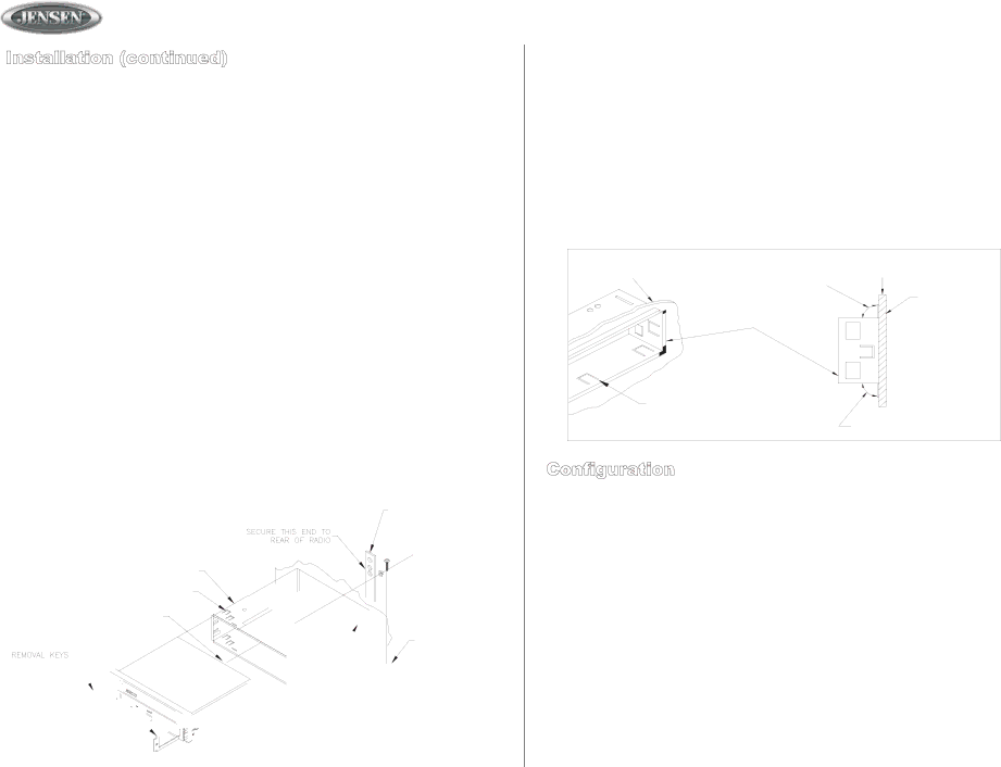
4)Locate the series of bend tabs along the top, bottom, and sides of the mounting sleeve. With the sleeve fully inserted into the dash opening, bend tabs outward so that the sleeve is firmly secured to the dashboard.
5)Carefully slide the radio into the mounting sleeve making sure it is right side up until it is fully seated and the spring clips lock it into place.
6)Attach one end of the perforated mounting strap (supplied) to the screw stud on the rear of the chassis using the flange nut provided. Fasten the other end of the perforated strap to a secure part of the dashboard, either above or below the radio using the screw and flange nut provided, bend the strap to position as necessary.
CAUTION: The rear of the radio must be supported with the strap to prevent damage to the dashboard from the weight of the radio or improper operation due to vibration.
JHD1000
Kit Installation
1.If your radio requires the use of an installation kit to mount this radio, follow the instructions included in the kit to attach the radio to the mounting plate supplied with the kit.
2.Wire and test the radio as described.
3.Install the radio/mounting plate assembly to the
4.Attach the support strap to the radio and dashboard as described in step 6 on page 2.
5.Replace the dashboard trim panel.
| M O UNTING TA B DE TA ILS |
|
C UTAW AY V IEW O F | TO P TA B B END | S IDE VIE W |
M OU NTING SU RFACE | ||
| U PW AR D 90 ° | M OU NTING |
|
| |
| M OUNT IN G | SURFACE |
|
| |
| S LEEVE |
|
B END TABS
B OTTO M TA B
B EN D DO W NW A RD 90 °
Configuration
The radio can be programmed to change options and factory settings. Follow the steps that follow to modify the unit as required.
Configuration of the Clock Display (12 or 24 Hour)
Press AUDIO ADJUST for more than three seconds. The unit will enter the general configuration menu and display
Configuration of Auxiliary Low-Level Audio Input
Press AUDIO ADJUST for more than three seconds. The unit will enter the general configuration menu. To configure the radio to accept
Note: If this feature is disabled, the front panel jack will also be disabled.
2
