
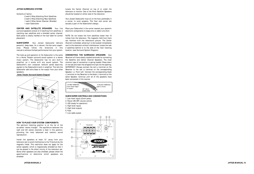
JHT525 specifications
The Jensen JHT525 is a versatile and powerful home theater projector designed to meet the demands of both casual users and audiophiles alike. This projector stands out with its impressive visual performance and advanced features, making it an ideal choice for anyone looking to enhance their home entertainment experience.At the heart of the Jensen JHT525 is its high-resolution projection capability. With a native resolution of 1920x1080 pixels, this projector delivers stunning full HD images that are crisp, clear, and vibrant. Coupled with a high contrast ratio, the JHT525 ensures deep blacks and luminous whites, resulting in a dynamic image quality that can truly bring movies and games to life.
One of the standout technologies featured in the JHT525 is its advanced LED light source. This technology not only extends the lifespan of the projector, with an estimated 30,000-hour operating time, but also provides consistent brightness and color accuracy. Users will appreciate the reduced maintenance that comes with LED, as there is no need for bulb replacements, making it both cost-effective and convenient.
The Jensen JHT525 also incorporates a range of connectivity options, ensuring compatibility with various devices. Equipped with multiple HDMI ports, USB connections, and even VGA inputs, this projector can easily connect to laptops, gaming consoles, and streaming devices, making it incredibly flexible for user needs. Additionally, the built-in multimedia player allows for direct playback of videos and presentations from USB drives.
For those who prioritize audio quality, the JHT525 comes with integrated speakers that produce rich sound, reducing the need for external audio systems for casual viewing. However, it also features audio output options for users who prefer to connect to high-end sound systems or external speakers for a more immersive experience.
Portability is another advantage of the Jensen JHT525. Its compact and lightweight design makes it easy to set up in any room, whether it's for a movie night or a business presentation. With a user-friendly interface and remote control, navigating settings and managing your content has never been easier.
In conclusion, the Jensen JHT525 is a feature-rich projector that combines high performance, advanced technology, and user-friendly design. Its impressive resolution, long-lasting LED light source, versatile connectivity, and integrated audio capabilities make it an excellent choice for anyone looking to create a captivating home theater experience. Whether for entertainment or professional use, the JHT525 is sure to impress.