INSTALLATION
F OR TAB L E TOP US E
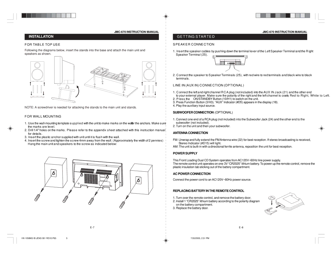
Following the diagrams below, insert the stands into the base and attach the main unit and speakers as shown.
NOTE: A screwdriver is needed for attacking the stands to the main unit and stands.
F OR WAL L MOUNTING
1.Use the
2.Drill 1/4" holes on the marks . P leas e refer to the appendix s heet attached with this ins truction manual for details .
3.Ins ert the plas tic anchor s upplied with unit until it is flus h with the wall.
4.Insert the screw and tighten the screw 4mm away from the wall. (Approximately the width of 2 pennies) Hang the main unit and s peakers to the s crew as indicated below:
E
G E T T ING S TA R T E D
S P E AK E R C ONNE C TION
1.Insert the speaker cables by pushing down the terminal lever of the Left S peaker Terminal and the R ight Speaker Terminal (25).
2.C onnect the s peaker to S peaker Terminals (25), with red wire to red terminals and black wire to black terminals .
L INE IN (A UX IN) C ONNE C T ION (OP T IONA L )
1.C onnect the left and right channel R C A plug (not included) into the AUX IN J ack (21) and the other end
to your external player. Make s ure the polarity of the right and the left channel is correct, Red to Right, White to Left.
2.P ress the ![]() ON/STANDBY Button (10/H1) to switch on the unit.
ON/STANDBY Button (10/H1) to switch on the unit.
3.Press Function Button (3/H3). “AUX” Indicator (#D5) appears in the display (18).
4.Play the auxiliary input source.
SUBWOOFER CONNECTION (OPTIONAL)
1.Connect one end of a RCA plug (not included) into the Subwoofer Jack (24) and the other end to the subwoofer (not included).
2.Turn on the unit and then your subwoofer.
ANTENNA CONNECTION
FM: Unwrap and fully extend the FMAntenna wire (22) for best reception. If stereo broadcasting is received,
Stereo Indicator (#D15) will light.
AM: The unit is
POWER SUPPLY
This Front Loading Dual CD System operates from AC120V~60Hz line power supply.
The remote control unit operates on one 3V “CR2025” lithium battery. To power up the remote control, remove the plastic insulation tab sticking out of the battery compartment.
AC POWER CONNECTION
Connect the power cord to an AC120V~60Hz power source.
REPLACING BATTERY IN THE REMOTE CONTROL
1. Turn over the remote control, and remove the battery door.
2.Install 1 “CR2025” lithium battery according to the polarity diagram on the battery compartment.
3.Replace the battery door.
E
5 |
| 7/20/2005, 2:51 PM | |
|