3.Slide the movable jaw by hand until the jaw contacts the workpiece.
4.Rotate the vise handwheel clockwise to re- engage the lead screw, and continue the tightening process of the jaw until the workpiece is securely clamped.
5.The quick release function can be used to back off the movable jaw when the cut is finished.
Miter Cuts
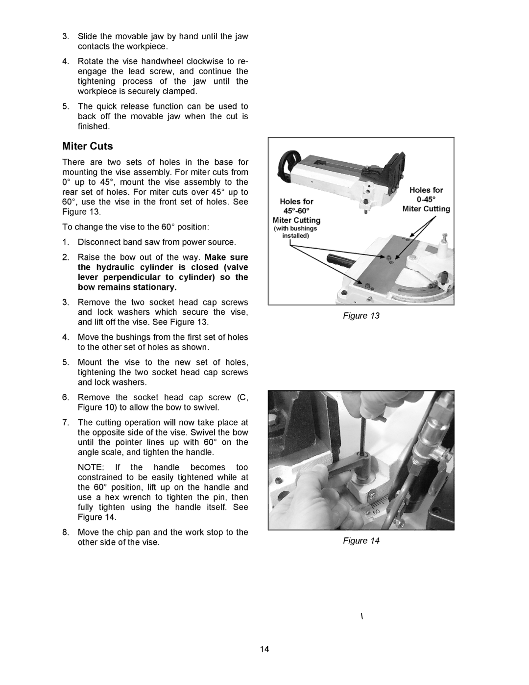
There are two sets of holes in the base for mounting the vise assembly. For miter cuts from 0° up to 45°, mount the vise assembly to the rear set of holes. For miter cuts over 45° up to 60°, use the vise in the front set of holes. See Figure 13.
To change the vise to the 60° position:
1.Disconnect band saw from power source.
2.Raise the bow out of the way. Make sure the hydraulic cylinder is closed (valve lever perpendicular to cylinder) so the bow remains stationary.
3.Remove the two socket head cap screws and lock washers which secure the vise, and lift off the vise. See Figure 13.
4.Move the bushings from the first set of holes to the other set of holes as shown.
5.Mount the vise to the new set of holes, tightening the two socket head cap screws and lock washers.
6.Remove the socket head cap screw (C, Figure 10) to allow the bow to swivel.
7.The cutting operation will now take place at the opposite side of the vise. Swivel the bow until the pointer lines up with 60° on the angle scale, and tighten the handle.
NOTE: If the handle becomes too constrained to be easily tightened while at the 60° position, lift up on the handle and use a hex wrench to tighten the pin, then fully tighten using the handle itself. See Figure 14.
8.Move the chip pan and the work stop to the other side of the vise.
Figure 13
Figure 14
\
14