Assembly of Band Saw
Tools required for assembly:
–cross point (Phillips) screwdriver
–3mm and 4mm hex wrenches (provided)
–1/2" and 9/16" wrenches
Remove any plastic or holding straps from around the band saw. Areas of the machine have been given a protective coating at the factory. This should be removed using a soft cloth moistened with kerosene or a cleaner- degreaser. Do not use gasoline, paint thinner, or lacquer thinner as these will damage painted surfaces. Do not use an abrasive pad.
Mounting Band Saw to Stand
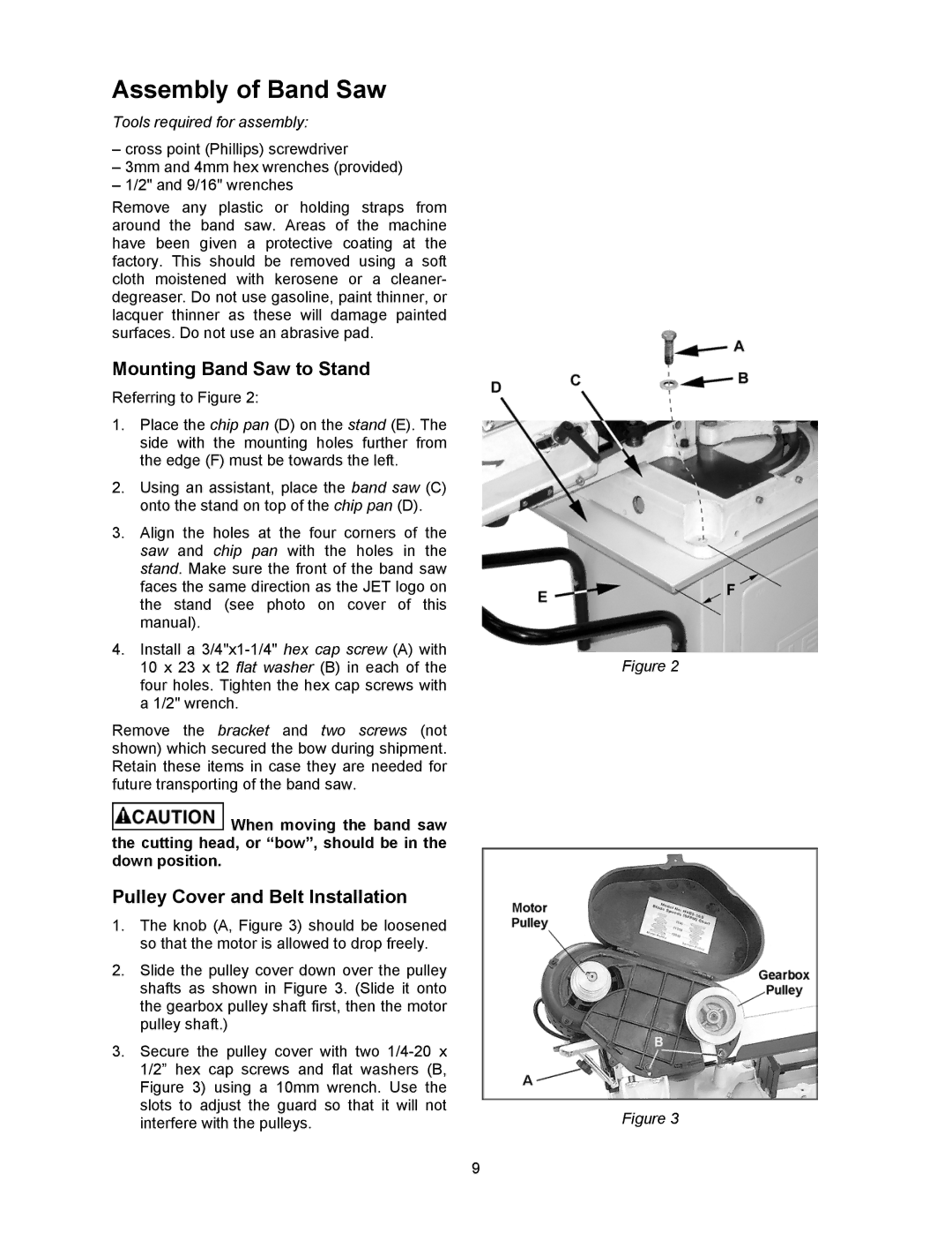
Referring to Figure 2:
1.Place the chip pan (D) on the stand (E). The side with the mounting holes further from the edge (F) must be towards the left.
2.Using an assistant, place the band saw (C) onto the stand on top of the chip pan (D).
3.Align the holes at the four corners of the saw and chip pan with the holes in the stand. Make sure the front of the band saw faces the same direction as the JET logo on the stand (see photo on cover of this manual).
4.Install a
Remove the bracket and two screws (not shown) which secured the bow during shipment. Retain these items in case they are needed for future transporting of the band saw.
![]() When moving the band saw the cutting head, or “bow”, should be in the down position.
When moving the band saw the cutting head, or “bow”, should be in the down position.
Pulley Cover and Belt Installation
1.The knob (A, Figure 3) should be loosened so that the motor is allowed to drop freely.
2.Slide the pulley cover down over the pulley shafts as shown in Figure 3. (Slide it onto the gearbox pulley shaft first, then the motor pulley shaft.)
3.Secure the pulley cover with two
9
Figure 2
Figure 3
