Changing Blades
![]() Blade teeth are sharp! Use care when handling the saw blade. Failure to comply may cause serious injury.
Blade teeth are sharp! Use care when handling the saw blade. Failure to comply may cause serious injury.
Note: The
1.Disconnect machine from power source.
2.Open both wheel covers (K, L, Fig. 9).
3.Loosen lock knob (G, Fig. 8) and pull exten- sion (O, Fig. 9) away from the table (C).
4.Remove rail guide (F, Fig. 5).
5.Release tension on the blade by moving the tension handle (V, Fig. 10) to the right.
Referring to Figure 9:
6.Remove blade (H) from upper and lower wheels (M, R) and from between the upper and lower blade guides (N, Q).
7.Remove the blade through the slot (P) in the table.
8.Guide the new blade through table slot (P) leading with the smooth edge. Place it around the upper and lower wheels and into the upper and lower blade guides (N, Q).
Note: The blade teeth should face the operator, and they should point down toward the table.
9.Position the blade to track in the middle of the rubber tires on the wheels (M, R).
10.Engage tension on the blade by moving the quick tension handle (V, Fig. 10) to the left.
11.Replace rail guide (F, Fig. 5).
Before operating the saw, check that the blade is tracking and has proper tension as described in Adjusting Blade Tension and Adjusting Blade Tracking below.
Adjusting Blade Tension
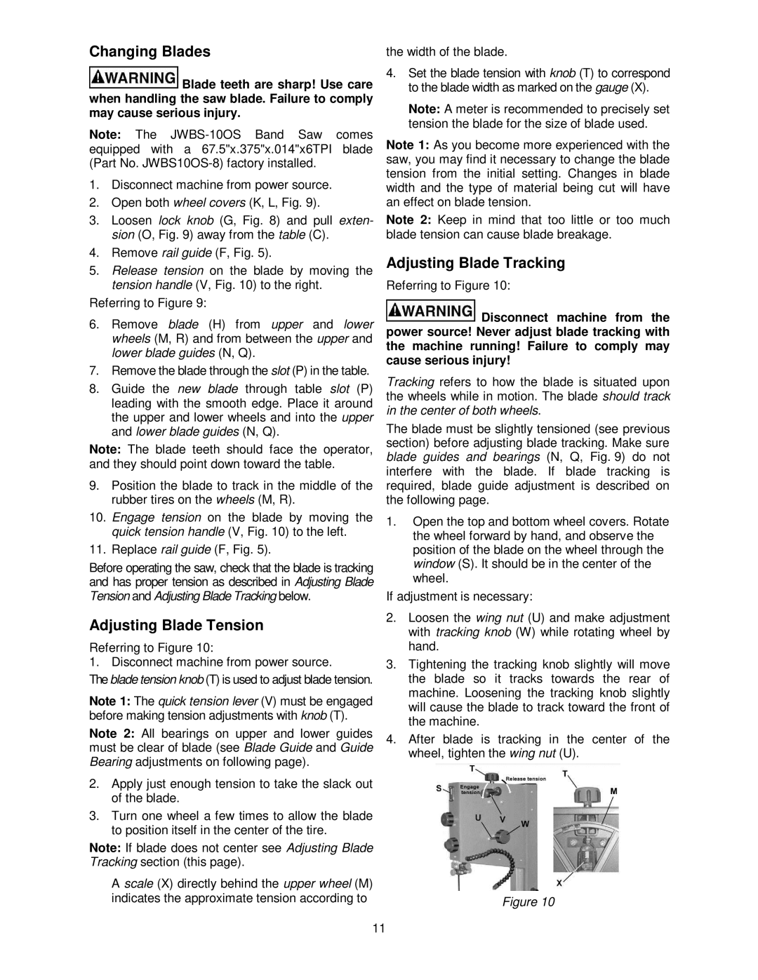
Referring to Figure 10:
1. Disconnect machine from power source.
The blade tension knob (T) is used to adjust blade tension.
Note 1: The quick tension lever (V) must be engaged before making tension adjustments with knob (T).
Note 2: All bearings on upper and lower guides must be clear of blade (see Blade Guide and Guide Bearing adjustments on following page).
2.Apply just enough tension to take the slack out of the blade.
3.Turn one wheel a few times to allow the blade to position itself in the center of the tire.
Note: If blade does not center see Adjusting Blade Tracking section (this page).
A scale (X) directly behind the upper wheel (M) indicates the approximate tension according to
the width of the blade.
4.Set the blade tension with knob (T) to correspond to the blade width as marked on the gauge (X).
Note: A meter is recommended to precisely set tension the blade for the size of blade used.
Note 1: As you become more experienced with the saw, you may find it necessary to change the blade tension from the initial setting. Changes in blade width and the type of material being cut will have an effect on blade tension.
Note 2: Keep in mind that too little or too much blade tension can cause blade breakage.
Adjusting Blade Tracking
Referring to Figure 10:
![]() Disconnect machine from the power source! Never adjust blade tracking with the machine running! Failure to comply may cause serious injury!
Disconnect machine from the power source! Never adjust blade tracking with the machine running! Failure to comply may cause serious injury!
Tracking refers to how the blade is situated upon the wheels while in motion. The blade should track in the center of both wheels.
The blade must be slightly tensioned (see previous section) before adjusting blade tracking. Make sure blade guides and bearings (N, Q, Fig. 9) do not interfere with the blade. If blade tracking is required, blade guide adjustment is described on the following page.
1.Open the top and bottom wheel covers. Rotate the wheel forward by hand, and observe the position of the blade on the wheel through the window (S). It should be in the center of the wheel.
If adjustment is necessary:
2.Loosen the wing nut (U) and make adjustment with tracking knob (W) while rotating wheel by hand.
3.Tightening the tracking knob slightly will move the blade so it tracks towards the rear of machine. Loosening the tracking knob slightly will cause the blade to track toward the front of the machine.
4.After blade is tracking in the center of the wheel, tighten the wing nut (U).
Figure 10
11