Upper Blade Guide Positioning
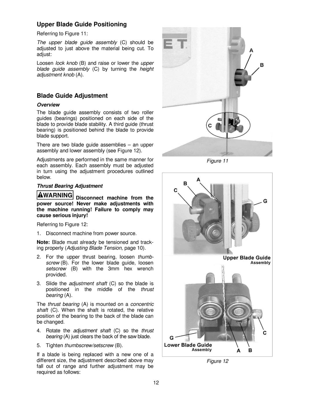
Referring to Figure 11:
The upper blade guide assembly (C) should be adjusted to just above the material being cut. To adjust:
Loosen lock knob (B) and raise or lower the upper blade guide assembly (C) by turning the height adjustment knob (A).
Blade Guide Adjustment
Overview
The blade guide assembly consists of two roller guides (bearings) positioned on each side of the blade to provide blade stability. A third guide (thrust bearing) is positioned behind the blade to provide blade support.
There are two blade guide assemblies – an upper assembly and lower assembly (see Figure 12).
Adjustments are performed in the same manner for each assembly. Each assembly must be adjusted in turn using the adjustment procedures outlined below.
Thrust Bearing Adjustment
![]() Disconnect machine from the power source! Never make adjustments with the machine running! Failure to comply may cause serious injury!
Disconnect machine from the power source! Never make adjustments with the machine running! Failure to comply may cause serious injury!
Referring to Figure 12:
1. Disconnect machine from power source.
Note: Blade must already be tensioned and track- ing properly (Adjusting Blade Tension, page 10).
2.For the upper thrust bearing, loosen thumb- screw (B). For the lower blade guide, loosen setscrew (B) with the 3mm hex wrench provided.
3.Slide the adjustment shaft (C) so the blade is positioned in the middle of the thrust bearing (A).
The thrust bearing (A) is mounted on a concentric shaft (C). When the shaft is rotated, the relative position of the bearing to the back of the blade can be changed.
4.Rotate the adjustment shaft (C) so the thrust bearing (A) just clears the back of the saw blade.
5.Tighten thumbscrew/setscrew (B).
If a blade is being replaced with a new one of a different size, the adjustment described above may fall out of range and further adjustment may be required as follows:
12
Figure 11
Figure 12