Installation
Tools required
7/16" and 1/2" wrenches Cross point screwdriver 3/16" hex wrench Adjustable square Hammer (or rubber mallet) Straight edge
The following instructions are for installing the XACTA Fence II and Rail System on JET Models
Figure 1
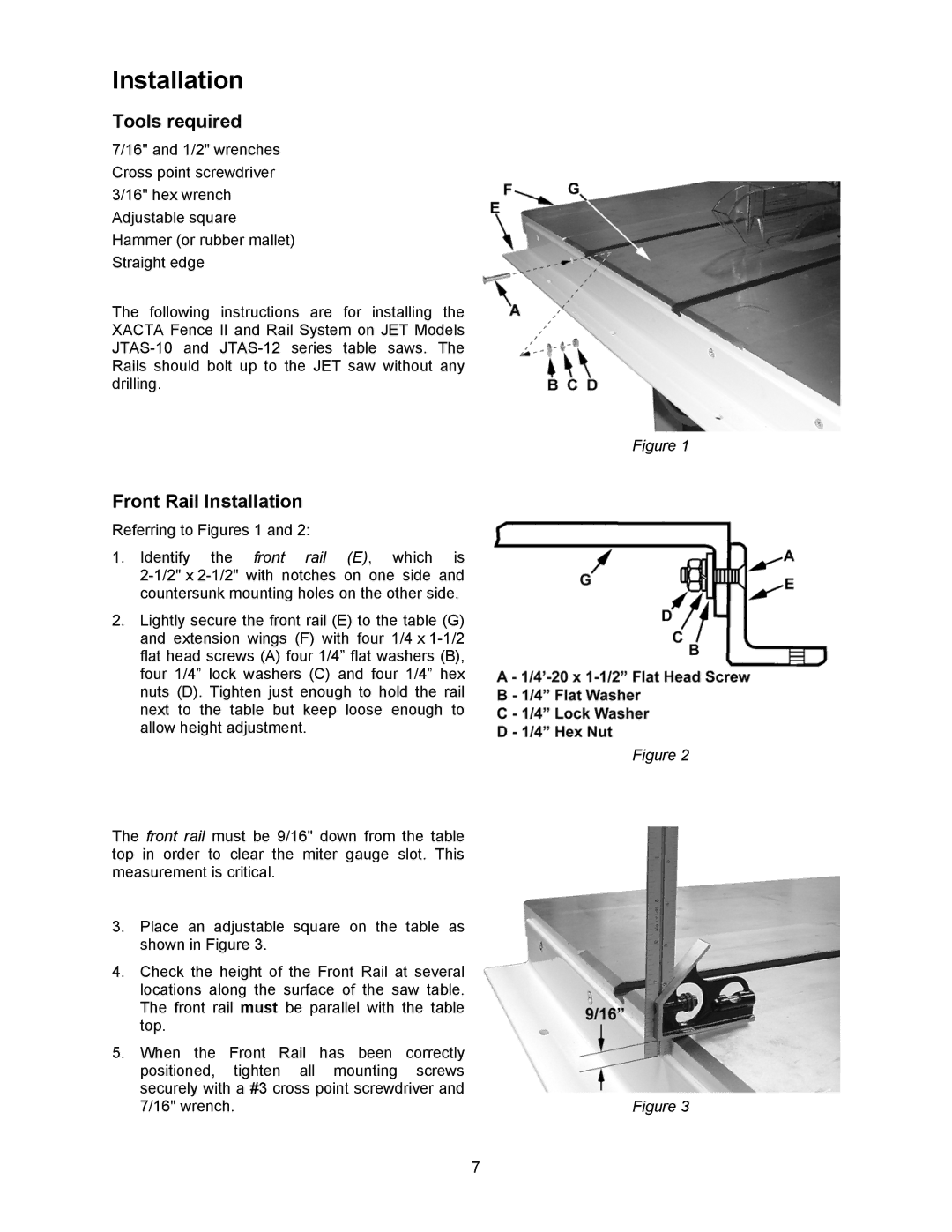
Front Rail Installation Referring to Figures 1 and 2:
1. Identify the front rail (E), which is
2.Lightly secure the front rail (E) to the table (G) and extension wings (F) with four 1/4 x
Figure 2
The front rail must be 9/16" down from the table top in order to clear the miter gauge slot. This measurement is critical.
3.Place an adjustable square on the table as shown in Figure 3.
4.Check the height of the Front Rail at several locations along the surface of the saw table. The front rail must be parallel with the table top.
5.When the Front Rail has been correctly positioned, tighten all mounting screws securely with a #3 cross point screwdriver and
7/16" wrench. | Figure 3 |
7