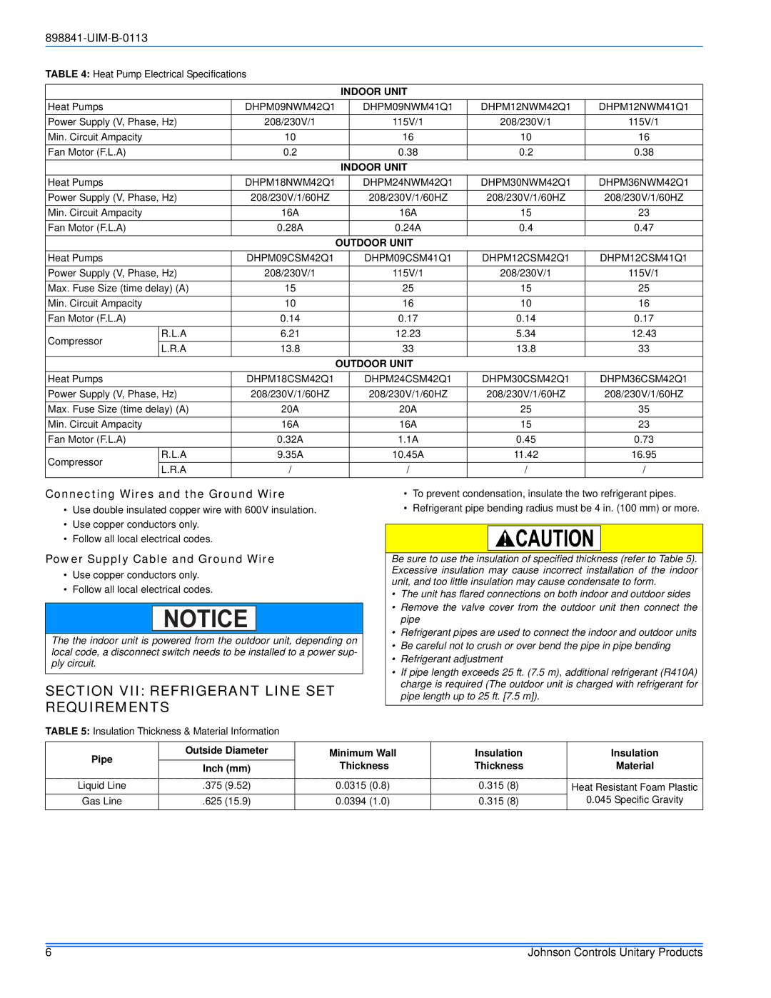
22 SEER specifications
Johnson Controls has long been a leader in the heating, ventilation, and air conditioning (HVAC) industry, consistently pushing the boundaries of energy efficiency and comfort. One of their standout offerings is the 22 SEER (Seasonal Energy Efficiency Ratio) air conditioning system, which boasts advanced technologies designed to deliver optimal performance while minimizing energy consumption.At the heart of the Johnson Controls 22 SEER system is its innovative compressor technology. The variable-speed compressor allows for precise temperature control by adjusting the cooling output according to the specific demands of your space. This means that instead of constantly turning on and off, the system can operate at lower speeds for longer periods, ensuring even cooling and reducing energy bills.
In addition to the compressor, the 22 SEER unit employs high-efficiency coils and a superior refrigeration system that work in tandem to enhance performance. These components are designed to maximize heat transfer, enabling the system to cool your home more effectively and efficiently.
Another notable feature of the Johnson Controls 22 SEER system is its smart technology integration. With a focus on convenience and energy management, these units often come equipped with Wi-Fi connectivity, allowing homeowners to control their HVAC systems remotely using a smartphone app. This capability enhances user experience by enabling real-time monitoring and scheduling, ultimately leading to smarter energy use.
The design of the units also reflects an emphasis on quiet operation. Noise reduction technologies, including sound-dampening features, ensure that the system operates quietly in the background, enhancing indoor comfort without disruptive sounds.
Durability is another standout characteristic of the Johnson Controls 22 SEER systems. These units are built with high-quality materials and rigorous testing standards, ensuring they can withstand harsh weather conditions and provide reliable performance over the years.
Moreover, the 22 SEER air conditioning systems contribute to environmental sustainability. By using less energy, they not only lower utility costs but also reduce the carbon footprint of homes, aligning with growing consumer preferences for eco-friendly solutions.
Overall, the Johnson Controls 22 SEER air conditioning system represents a significant leap forward in HVAC technology. Its blend of efficiency, innovative features, and user-friendly technologies makes it an ideal choice for environmentally-conscious homeowners seeking comfort without compromise. Whether upgrading an existing system or investing in a new one, the 22 SEER unit stands out as a prime example of luxury, efficiency, and sustainability in the HVAC market.

