898841-UIM-B-0113

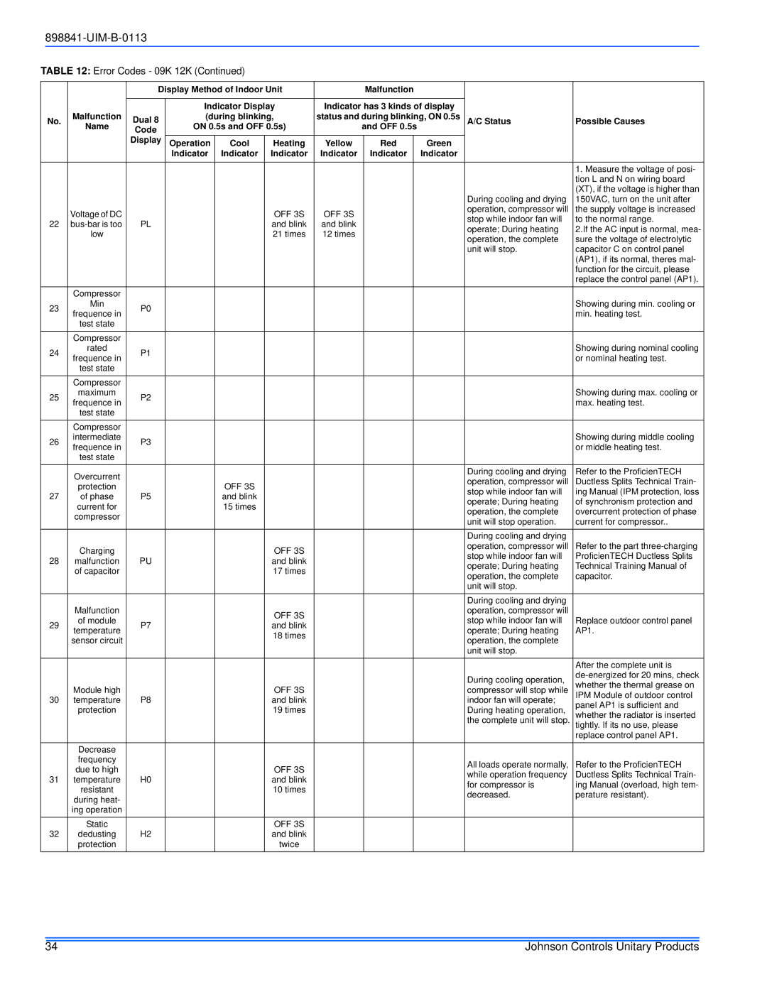
TABLE 12: Error Codes - 09K 12K (Continued)


Display Method of Indoor Unit


Malfunction


Malfunction


Indicator Display

Indicator has 3 kinds of display


No.

Dual 8

(during blinking,

status and during blinking, ON 0.5s

A/C Status

Possible Causes


Name

Code

ON 0.5s and OFF 0.5s)


and OFF 0.5s


Display

Operation

Cool

Heating

Yellow


Red


Green


Indicator

Indicator

Indicator

Indicator


Indicator


Indicator


1. Measure the voltage of posi-


tion L and N on wiring board


(XT), if the voltage is higher than


During cooling and drying

150VAC, turn on the unit after


Voltage of DC


OFF 3S

OFF 3S


operation, compressor will

the supply voltage is increased


stop while indoor fan will

to the normal range.

22

bus-bar is too

PL


and blink

and blink


operate; During heating

2.If the AC input is normal, mea-


low


21 times

12 times


operation, the complete

sure the voltage of electrolytic


unit will stop.

capacitor C on control panel


(AP1), if its normal, theres mal-


function for the circuit, please


replace the control panel (AP1).


Compressor


23

Min

P0


Showing during min. cooling or

frequence in


min. heating test.


test state


Compressor


24

rated

P1


Showing during nominal cooling

frequence in


or nominal heating test.


test state


Compressor


25

maximum

P2


Showing during max. cooling or

frequence in


max. heating test.


test state


Compressor


26

intermediate

P3


Showing during middle cooling

frequence in


or middle heating test.


test state


Overcurrent


During cooling and drying

Refer to the ProficienTECH


operation, compressor will

Ductless Splits Technical Train-


protection


OFF 3S


27


stop while indoor fan will

ing Manual (IPM protection, loss

of phase

P5


and blink


operate; During heating

of synchronism protection and


current for


15 times


operation, the complete

overcurrent protection of phase


compressor


unit will stop operation.

current for compressor..


During cooling and drying


Charging


OFF 3S


operation, compressor will

Refer to the part three-charging


stop while indoor fan will

ProficienTECH Ductless Splits

28

malfunction

PU


and blink


operate; During heating

Technical Training Manual of


of capacitor


17 times


operation, the complete

capacitor.


unit will stop.


During cooling and drying


Malfunction


OFF 3S


operation, compressor will


29

of module


stop while indoor fan will

Replace outdoor control panel

P7


and blink


temperature


operate; During heating

AP1.


18 times


sensor circuit


operation, the complete


unit will stop.


After the complete unit is


During cooling operation,

de-energized for 20 mins, check


whether the thermal grease on


Module high


OFF 3S


compressor will stop while

30

P8


IPM Module of outdoor control

temperature


and blink


indoor fan will operate;

panel AP1 is sufficient and


protection


19 times


During heating operation,


whether the radiator is inserted


the complete unit will stop.


tightly. If its no use, please


replace control panel AP1.


Decrease


frequency


All loads operate normally,

Refer to the ProficienTECH


due to high


OFF 3S


31


while operation frequency

Ductless Splits Technical Train-

temperature

H0


and blink


for compressor is

ing Manual (overload, high tem-


resistant


10 times


decreased.

perature resistant).


during heat-


ing operation


Static


OFF 3S


32

dedusting

H2


and blink


protection


twice


34

Johnson Controls Unitary Products

Page 34
Image 34
Johnson Controls 22 SEER installation manual During cooling and drying 150VAC, turn on the unit after

22 SEER specifications

Johnson Controls has long been a leader in the heating, ventilation, and air conditioning (HVAC) industry, consistently pushing the boundaries of energy efficiency and comfort. One of their standout offerings is the 22 SEER (Seasonal Energy Efficiency Ratio) air conditioning system, which boasts advanced technologies designed to deliver optimal performance while minimizing energy consumption.

At the heart of the Johnson Controls 22 SEER system is its innovative compressor technology. The variable-speed compressor allows for precise temperature control by adjusting the cooling output according to the specific demands of your space. This means that instead of constantly turning on and off, the system can operate at lower speeds for longer periods, ensuring even cooling and reducing energy bills.

In addition to the compressor, the 22 SEER unit employs high-efficiency coils and a superior refrigeration system that work in tandem to enhance performance. These components are designed to maximize heat transfer, enabling the system to cool your home more effectively and efficiently.

Another notable feature of the Johnson Controls 22 SEER system is its smart technology integration. With a focus on convenience and energy management, these units often come equipped with Wi-Fi connectivity, allowing homeowners to control their HVAC systems remotely using a smartphone app. This capability enhances user experience by enabling real-time monitoring and scheduling, ultimately leading to smarter energy use.

The design of the units also reflects an emphasis on quiet operation. Noise reduction technologies, including sound-dampening features, ensure that the system operates quietly in the background, enhancing indoor comfort without disruptive sounds.

Durability is another standout characteristic of the Johnson Controls 22 SEER systems. These units are built with high-quality materials and rigorous testing standards, ensuring they can withstand harsh weather conditions and provide reliable performance over the years.

Moreover, the 22 SEER air conditioning systems contribute to environmental sustainability. By using less energy, they not only lower utility costs but also reduce the carbon footprint of homes, aligning with growing consumer preferences for eco-friendly solutions.

Overall, the Johnson Controls 22 SEER air conditioning system represents a significant leap forward in HVAC technology. Its blend of efficiency, innovative features, and user-friendly technologies makes it an ideal choice for environmentally-conscious homeowners seeking comfort without compromise. Whether upgrading an existing system or investing in a new one, the 22 SEER unit stands out as a prime example of luxury, efficiency, and sustainability in the HVAC market.